Injection molding die of equal-diameter both-way plastic helical gear

An injection molding, helical gear technology, applied in the direction of gears, household appliances, other household appliances, etc., can solve the problems of difficult pilot hole processing, poor molding quality, large resistance to core rotation, etc., to achieve automatic demoulding, improve Forming efficiency and reliable action

Active Publication Date: 2017-05-10
宁波明旌电子有限公司
View PDF3 Cites 9 Cited by
  • Summary
  • Abstract
  • Description
  • Claims
  • Application Information

AI Technical Summary

Problems solved by technology

Aiming at the problem of demoulding after injection molding of herringbone gears (equivalent to bidirectional plastic helical gears with equal diameters), in current practice, mandrels are set in the movable and fixed molds respectively to form helical tooth grooves (the number of core rods is equal to the number of helical tooth grooves). Quantity), after the mold is opened, the connecting rod device drives the forming core rod of the helical groove to pull out obliquely, so as to realize the two-way core pulling of the movable and fixed mold, but the mold structure is complex, the parts processing is cumbersome, the assembly accuracy is low, and the molding quality is poor
[0004] There is also an injection mold structure that adopts two helical gear cavities to be embedded in combination, fixed mold plate rotation to push out, arc-shaped bent pins to reset, and movable mold core to rotate in two stages, but this structure has at least the following deficiencies: 1. On the fixed mold cavity It is difficult to process the guide hole of the curved pin; 2. It is difficult to control the consistency between the radian of the curved pin and the rotation angle of the fixed mold cavity; 3. The resistance of the core rotation is large and it is easy to wear; 4. It is not easy to ensure the rotation of the core The angle and speed are consistent with the helix angle of the helical gear; 5. The movement of the secondary push-out mechanism is not flexible

Method used


Image

  • Injection molding die of equal-diameter both-way plastic helical gear
  • Injection molding die of equal-diameter both-way plastic helical gear
  • Injection molding die of equal-diameter both-way plastic helical gear

Examples


Embodiment Construction

[0045] In order to facilitate the understanding of those skilled in the art, the present invention will be further described below in conjunction with the embodiments and accompanying drawings.

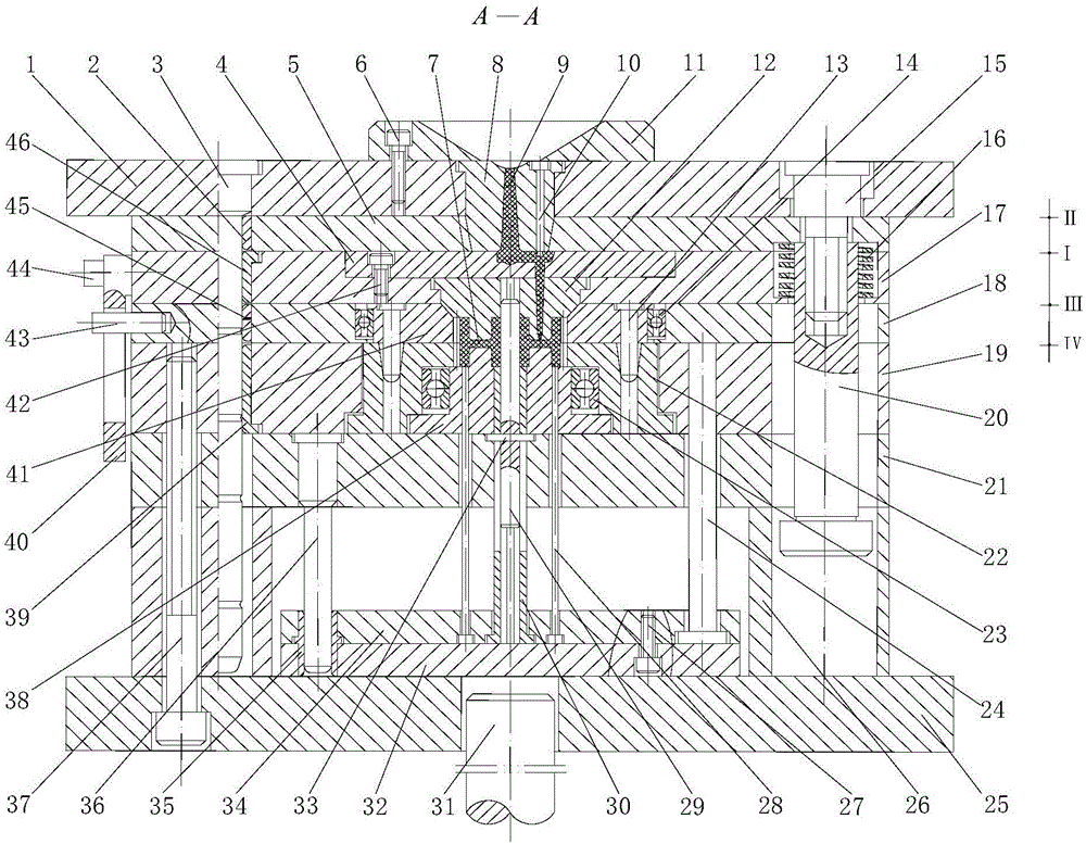
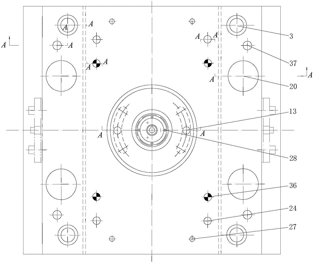
[0046] Such as figure 1 , figure 2 as shown, figure 2 It mainly reflects the distribution positions of parts such as guide post 3, hexagon socket head cap screw, ball guide pin 13, push rod 28, reset rod 24, push plate guide post 36, limit pull rod 20 and the like. From top to bottom, it includes: fixed mold seat plate 1, de-casting plate 5, core fixed plate 17, cavity fixed plate 18, movable template 19, support plate 21, cushion block 26, movable mold bottom plate 25;

[0047] There is a positioning ring 11 on the top of the fixed mold seat plate 1, and a pressure plate 4 is embedded in the upper surface of the core fixing plate 17. Below the pressure plate 4, a No. The core insert 12 and the No. I helical gear cavity insert 41 are arranged inside the cavity fixing plate 18; th...


PUM


Abstract

The invention discloses an injection molding die of an equal-diameter both-way plastic helical gear. The injection molding die sequentially comprises a fixed die seat plate, a pouring stopping plate, a mold core fixing plate, a cavity fixing plate, a movable die plate, a bearing plate, a mat block and a movable die base plate from top to bottom; a positioning ring is arranged above the fixed die seat plate; a first centripetal thrust bearing and a first helical gear cavity insert are arranged inside the cavity fixing plate; a second helical gear cavity insert, a second centripetal thrust bearing and a second mold core insert are arranged inside the movable die plate; and a bulb guide pin is installed inside the first helical gear cavity insert, a guide hole is formed inside the second helical gear cavity insert, and the first helical gear cavity insert and the second helical gear cavity insert are subject to helical gear groove position alignment through the bulb guide pin and the guide hole. The injection molding die is perfect in structure, efficient in motion and high in molding quality; multiple parting line sequenced parting achieves material coagulating of a gating system and automatic demolding of a helical gear plastic piece, the molding efficiency of the plastic piece is improved, and the service life of the die is prolonged.

Description

technical field [0001] The invention relates to a mold structure for injection molding of plastic helical gears, and more specifically relates to the design and application of a mold structure for injection molding of equal-diameter bidirectional plastic helical gears. Background technique [0002] Equal-diameter two-way plastic helical gear is a cylindrical gear with right-handed teeth on one part of the tooth width and left-handed teeth on the other part of the tooth width, commonly known as herringbone gears. The herringbone gear is equivalent to the combination of two helical gears. The structure is symmetrical, the diameter is equal, and the direction of the helix angle is opposite. It not only has the advantages of helical gears, but also overcomes the disadvantage of large axial force generated by helical gears. It has load-carrying capacity. High, stable transmission and small axial load, herringbone gear transmission is an important development direction of gear tra...

Claims


Application Information

Patent Timeline
Patent Type & Authority Applications(China)
IPC IPC(8): B29C45/26B29C45/40B29C45/66B29L15/00
CPCB29C45/2606B29C45/4005B29C45/66B29L2015/003
Inventor 江昌勇江妦黄志荣李丹虹姜伯军
Owner 宁波明旌电子有限公司
Why Eureka
Try Eureka