Wire tapping control system and trolley pole with system

A control system and a rod cavity technology, applied in the field of wiring control systems and collector rods, can solve the problem of low degree of automation, and achieve the effect of meeting the needs of actual working conditions, high control precision and sufficient power

Pending Publication Date: 2017-05-10
SUZHOU KAIBO YIKONG DRIVE TECH CO LTD
View PDF0 Cites 0 Cited by
  • Summary
  • Abstract
  • Description
  • Claims
  • Application Information

AI Technical Summary

Problems solved by technology

[0007] In the process of connecting the current collecting rods in the prior art, when the vehicle does not stop at the specified position, that is, when the collecting head is not in the space radiated by the catcher during the rising process, this method of automatically connecting the wire network cannot meet the requirements , the current collector cannot be successfully connected to the wire network, and the driver needs to get off the car to manually connect the wire network, and the degree of automation is not high

Method used


Image

  • Wire tapping control system and trolley pole with system
  • Wire tapping control system and trolley pole with system

Examples


Embodiment 1

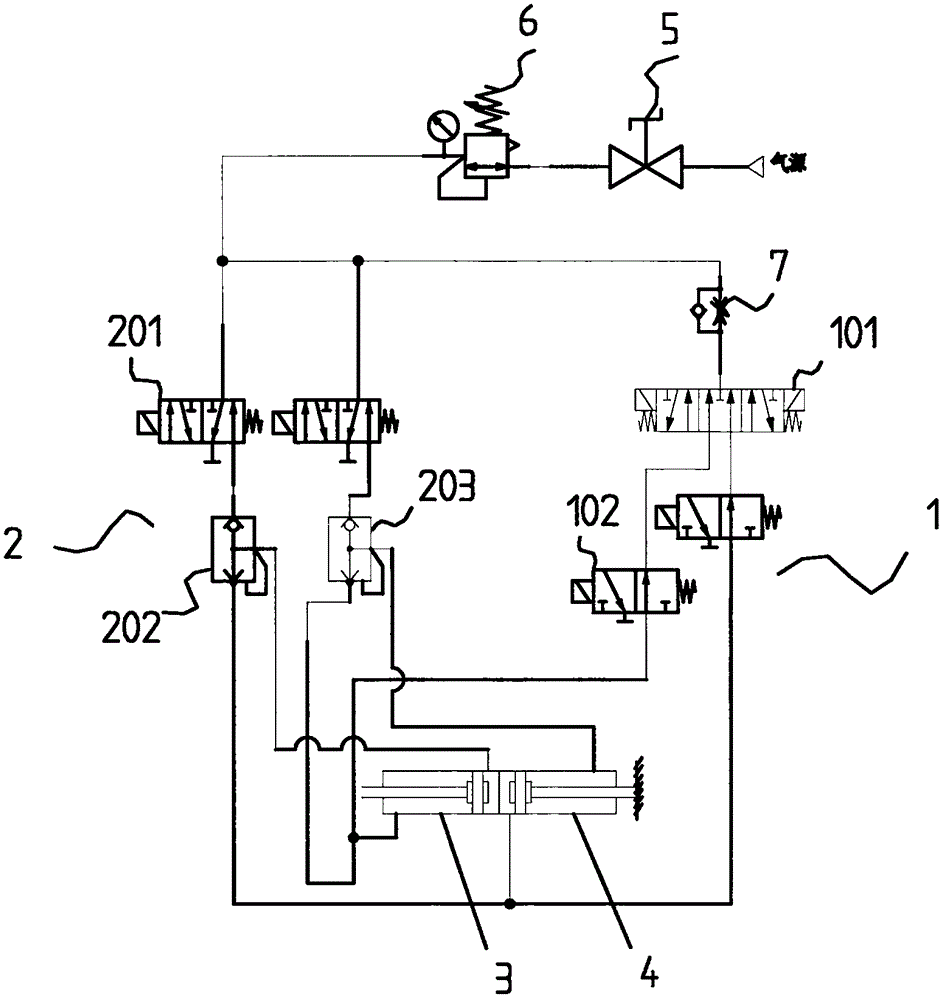
[0040] The first type of wiring control system for collector poles includes an air source, which is usually supplied by the vehicle itself, and is connected to the air source through an air pipe, and the centering system 2 and the swing system 1 are connected at the end of the air pipe. Wherein the centering system 2 is connected in parallel with the swinging system 1, that is, branch pipeline one and branch pipeline two are formed from the end of the trachea, the centering system 2 is arranged on the branch pipeline one, and the swinging system 1 is mainly Arranged on the second branch pipeline, and merge the airflow of the swing system 1 into the return system 2.

[0041] The centering system 2 includes a solenoid valve 201, the input end of the solenoid valve is connected to the end of the branch pipeline 1, and the left and right pipelines are arranged on the solenoid valve, which are the first pipeline and the second pipeline, Wherein, the first pipeline is connected with...

Embodiment 2

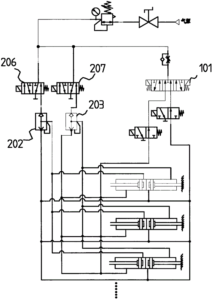
[0065] The second take-up control system for collector poles is the same as Embodiment 1, including an air source, a centering system 2 and a swing system 1 connected to the air source through a gas pipe, and the centering system 2 includes a control system unit, the control unit is composed of a solenoid valve 1 206 and a solenoid valve 2 207, and the air pipe end part is divided into a branch pipeline 1, a branch pipeline 2 and a branch pipeline 3, the branch pipeline 1 is connected with the solenoid valve 1 206, and the branch pipeline Road two is connected with solenoid valve two 207, and branch pipeline three is connected with swing system 1.

[0066] Solenoid valve one 206 is connected with the first intake selection valve 202, solenoid valve two 207 is connected with the second intake selection valve 203, the first selection valve is connected with the first air passage 204 and the second air passage 205, the second intake selection valve The gas selection valve 203 is ...


PUM


Abstract

The invention discloses a wire tapping control system and relates to the technical field of trolley bus control. The wire tapping control system comprises a cylinder set, a recentralizing system and a swinging system, wherein the cylinder set is composed of cylinders which are back-to-back connected with each other; an air circuit output of the swinging system is merged into an output air circuit of the recentralizing system; an output terminal of the recentralizing system is communicated with a rod chamber and a rod-less chamber of the cylinders; the recentralizing system and the swinging system are in parallel connection on the output air circuit of an air source; and the recentralizing system is capable of independently controlling the route of the cylinder set or jointly controlling with the swinging system. The invention also relates to a trolley pole with the system. The system can be utilized to realize the swinging of the trolley pole, reduce the requirements for the stopping positions of the vehicle and the wire grid and increase the intelligent effect.

Description

technical field [0001] The invention relates to the technical field of trolleybus control vehicles, and mainly relates to a line-taking control system and a collector pole with the system, which can make the collector pole realize centering and swinging actions. Background technique [0002] Ordinary trolleybuses can be seen everywhere in many cities in our country, but due to the disadvantages of poor flexibility, complicated routes and occupying urban space, they are gradually marginalized under the trend of rapid popularization of automobiles and competition from fuel buses. [0003] In recent years, under the serious situation of increasing urban air pollution and increasing dependence on foreign oil, traditional fuel-powered buses can no longer meet the needs of energy conservation and emission reduction. The country has begun to vigorously promote new energy buses. [0004] The emergence of dual-source trolleybuses not only overcomes the natural defects of ordinary tro...

Claims


Application Information

Patent Timeline
Patent Type & Authority Applications(China)
IPC IPC(8): B60L5/32
CPCB60L5/32
Inventor 郝庆军
Owner SUZHOU KAIBO YIKONG DRIVE TECH CO LTD
Why Eureka
Try Eureka