Rear-row seat folding mechanism capable of giving way backwards

A technology of folding mechanism and rear seat, which is applied to detachable/non-detachable seats, vehicle seats, movable seats, etc., can solve the problems of poor applicability, troublesome operation and high cost, and achieves simple operation and easy production. , the effect of low cost

Inactive Publication Date: 2017-05-10
MAGNA SEATING (TAIZHOU) CO LTD
View PDF6 Cites 2 Cited by
  • Summary
  • Abstract
  • Description
  • Claims
  • Application Information

AI Technical Summary

Problems solved by technology

[0005] The problem to be solved by the present invention is to overcome the disadvantages of troublesome operation, poor applicability and high cost in the folding mechanism of the backrest of the prior art, and propose a rear seat that is easy to operate, easy to advance and retreat, flexible to maneuver and beautiful in appearance. Seat back folding mechanism

Method used


Image

  • Rear-row seat folding mechanism capable of giving way backwards
  • Rear-row seat folding mechanism capable of giving way backwards
  • Rear-row seat folding mechanism capable of giving way backwards

Examples


Embodiment 1

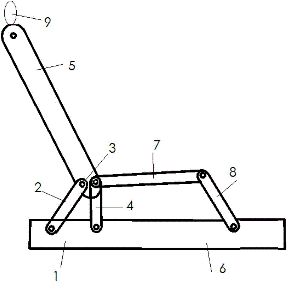
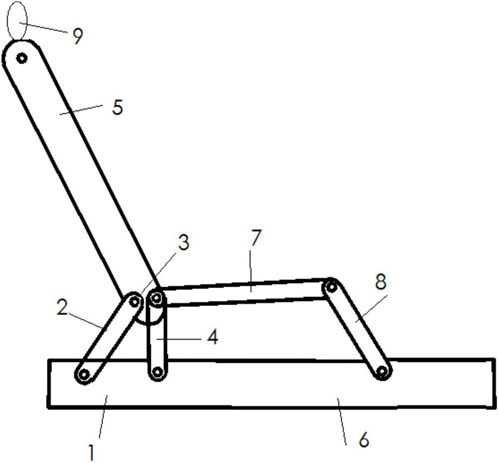
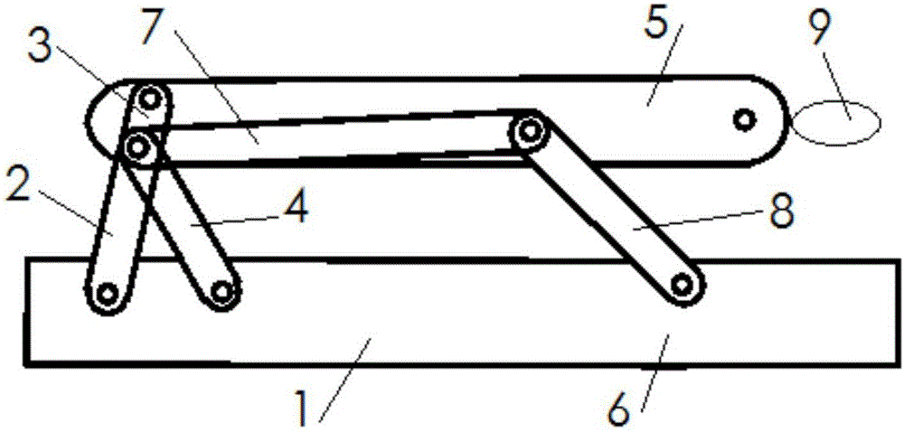
[0027] Embodiment 1: as figure 1 As shown, a rear seat folding mechanism that can give way to the rear, the folding structure is composed of two hinged four-bar mechanisms, both of which are double rocker mechanisms, of which the first hinged four-bar mechanism is composed of Frame one 1, connecting rod one 2, connecting rod one 3 and connecting rod two 4 are sequentially hinged to form, frame one 1 is fixedly connected with the seat base, and connecting rod one 3 is fixedly connected with the support of the seat back 5 as One; the second hinged four-bar mechanism is composed of frame two 6, connecting rod two 4, connecting rod two 7 and connecting rod three 8, and the frame two 6 is fixedly connected with frame one 1 as a whole, connected The rear end of rod two 7 is hingedly connected with the upper end of connecting rod two 4 and the front end of connecting rod one 3, the front end of connecting rod two 7 is hingedly connected with the upper end of connecting rod three 8, a...

Embodiment 2

[0033] Embodiment 2: Let the length of frame one 1 be a, the length of connecting rod one 2 be b, the length of connecting rod one 3 be c, and the length of connecting rod two 4 be d, wherein a=b, d 2 =a 2 +ac+c 2 . The said lengths all refer to the distance between the hinge holes. When the connecting rod-2 and the connecting rod-3 are in a straight line, the angle between the connecting rod-2 and the frame-1 is just 60°, and the rest of the structures are the same as in the embodiment 1. As the hinged four-bar mechanism generally adopts analytical method, graphical method or experimental method in the design, each method has its own advantages and disadvantages. After some appropriate selection and limitation of the length of the member, the design process can be simplified and the design requirements can be guaranteed. ,Improve efficiency.


PUM


Abstract

The invention provides a rear-row seat folding mechanism capable of giving way backwards. The rear-row seat folding mechanism capable of giving way backwards is formed by compounding two hinge four-rod mechanisms, wherein the first hinge four-rod mechanism is formed by hinging a frame I, a frame connecting rod I, a connecting rod I and a frame connecting rod II in sequence; the frame I is fixedly connected with a seat base; the connecting rod I is integrally connected with a bracket of a seat backrest in a fixed manner; the second hinge four-rod mechanism is formed by hinging a frame II, the frame connecting rod II, a connecting rod II and a frame connecting rod III in sequence; the frame II is integrally connected with the frame I in a fixed manner; the rear end of the connecting rod II is hinged with the upper end of the frame connecting rod II and the front end of the connecting rod I; and the front end of the connecting rod II is hinged with the upper end of the frame connecting rod III. The rear-row seat folding mechanism capable of giving way backwards has the advantages of simple structure, simple and convenient operation, less machining amount, low cost, flexibility and beautiful appearance and is especially suitable for seat adjusting devices for small vehicles.

Description

technical field [0001] The invention belongs to the technical field of seat structures, and in particular relates to a folding mechanism of a vehicle seat. Background technique [0002] In the existing vehicle seats, the rear seat backrests interfere with the front backrests when the backrests are folded due to the narrow space of the vehicle body, and the backrests of the rear seats cannot be folded down normally. The technical solution is to either remove the headrest and then put down the backrest; or adjust the headrest to the lowest position and then put it down, this method is limited to the L-shaped headrest; or set the headrest to have automatic folding Features. [0003] The above-mentioned first solution is cumbersome to operate, and the removed headrest has no suitable fixing place and is easy to lose; the second solution is only effective for L-shaped headrests. When using the headrest, an L-shaped Grooves, poor appearance; the third option is expensive. [00...

Claims


Application Information

Patent Timeline
Patent Type & Authority Applications(China)
IPC IPC(8): B60N2/20B60N2/30
CPCB60N2/203B60N2/3009
Inventor 黄健薛磊
Owner MAGNA SEATING (TAIZHOU) CO LTD
Why Eureka
Try Eureka