Method for Preventing Axlebox Bearing from Abrasion by Adjusting Rubber Layer Thickness and Rotary Arm Node

A technology of axle box bearings and rubber layers, which is applied in the field of locomotive parts manufacturing, and can solve problems such as axle bearing wear

Active Publication Date: 2019-01-22
ZHUZHOU TIMES RUIWEI ANTI VIBERATION EQUIP LTD
View PDF10 Cites 0 Cited by
  • Summary
  • Abstract
  • Description
  • Claims
  • Application Information

AI Technical Summary

Problems solved by technology

[0011] The purpose of the present invention is to propose a method for preventing or reducing the wear of the locomotive axle bearing and the joint of the joint of the joint of the joint of the joint of the joint of the joint of the joint of the joint of the joint of the joint of the joint of the joint of the joint of the joint of the joint of the joint of the joint of the joint of the joint

Method used


Image

  • Method for Preventing Axlebox Bearing from Abrasion by Adjusting Rubber Layer Thickness and Rotary Arm Node
  • Method for Preventing Axlebox Bearing from Abrasion by Adjusting Rubber Layer Thickness and Rotary Arm Node

Examples


Embodiment 1

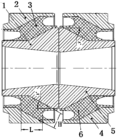
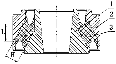
[0056] attached figure 1 and 2 A specific embodiment of the present invention is given; a pivoting arm node, the pivoting arm node is formed by the combination of two elastic rubber parts with symmetrical structure, including the left metal outer casing 2 and the left metal inner casing 1, and the left metal outer casing 2 and the left metal inner casing There is a left rubber layer 3 integrally vulcanized between the left metal inner sleeve 1, and a right metal outer sleeve 4 and a right metal inner sleeve 5, and a right rubber layer 6 is integrally vulcanized between the right metal outer sleeve 4 and the right metal inner sleeve 5; The inner holes of the inner sleeve 1 and the right metal inner sleeve 5 are respectively arranged as tapered holes facing each other, that is, the big head of the tapered hole is outside, and the small head of the tapered hole is close to each other on the inside; it is characterized in that the left rubber layer 3 and the right The rubber laye...

Embodiment 2

[0058] The structure of the second embodiment is basically the same as that of the first embodiment, except that the thickness of the added rubber layer is different. The thickness of the rubber layer at the joint of the boom is controlled at 25-28mm; the length of the rubber layer is controlled at 38-45mm.

Embodiment 3

[0060] The structure of the third embodiment is basically the same as that of the first embodiment, except that the thickness of the added rubber layer is different. The thickness of the rubber layer at the joint of the pivoting arm is controlled at 27 mm; the length of the rubber layer is controlled at 40 mm.


PUM

PropertyMeasurementUnit
Thicknessaaaaaaaaaa
Lengthaaaaaaaaaa

Abstract

The invention discloses a method for adjusting the thickness of rubber layers to prevent an axle box bearing from being abraded and tumbler joints. The method for adjusting the thickness of the rubber layers to prevent the axle box bearing from being abraded comprises the steps that a combination structure of two conical inner hole tumbler joints is adopted, and the longitudinal rigidity, axial rigidity, torsional rigidity and deflection rigidity of the tumbler joints are changed by increasing the thickness of the tumbler joint rubber layers, so that the longitudinal rigidity and the deflection rigidity of the tumbler joints are lowered; meanwhile, the torsional rigidity is prevented from being lowered by increasing the axial rigidity, and axle bearing abrasion is effectively lowered; the thickness of the left and right rubber layers is 22-30 mm, and the length of the left and right rubber layers is 35-60 mm. The longitudinal rigidity, axial rigidity, torsional rigidity and deflection rigidity of the tumbler joints are changed by increasing the thickness of the tumbler joint rubber layers, and the longitudinal rigidity and the deflection rigidity of the tumbler joints are lowered; meanwhile, by increasing the axial rigidity, the torsional rigidity is prevented from being lowered, and the axle bearing abrasion is effectively lowered.

Description

technical field [0001] The invention relates to a method and device for adjusting the performance of locomotive parts, in particular to a method for preventing or reducing the wear of the locomotive axle box bearings by changing the performance of the locomotive pivot arm nodes and the pivot arm nodes for improving the performance of the locomotive axle box. The service life of the bearing. It belongs to the technical field of locomotive parts manufacturing. Background technique: [0002] The pivoting arm axle box positioning method is a traditional axle box positioning method, which is widely used in light rail, subway, ordinary passenger cars and high-speed EMU bogies. The so-called rotating arm type axle box positioning is that the axle box and the positioning rotating arm are combined to form a rotating arm shaft, and the axle box and the positioning pull rod are integrated to form a rotating arm structure. The positioning of the pivoting arm of the axle box is connect...

Claims


Application Information

Patent Timeline
IPC IPC(8): B61F5/26
Inventor 蒋仲三冯万盛林胜谢彦飞黄江彪雷军玉
Owner ZHUZHOU TIMES RUIWEI ANTI VIBERATION EQUIP LTD
Why Eureka
Try Eureka