Faucet oil pressure brake device

A faucet and brake technology, used in bicycle accessories, bicycle brakes, etc., can solve the problems of the large brake master cylinder and the inability to match the concealment of the brake line.

Active Publication Date: 2017-05-10
TEKTRO TECH
View PDF5 Cites 1 Cited by
  • Summary
  • Abstract
  • Description
  • Claims
  • Application Information

AI Technical Summary

Problems solved by technology

[0003] However, the brake master cylinder is too bulky to match the design of the brake line hidden in the frame

Method used


Image

  • Faucet oil pressure brake device
  • Faucet oil pressure brake device
  • Faucet oil pressure brake device

Examples


Embodiment Construction

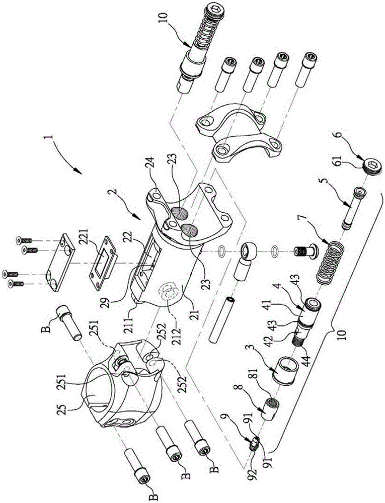
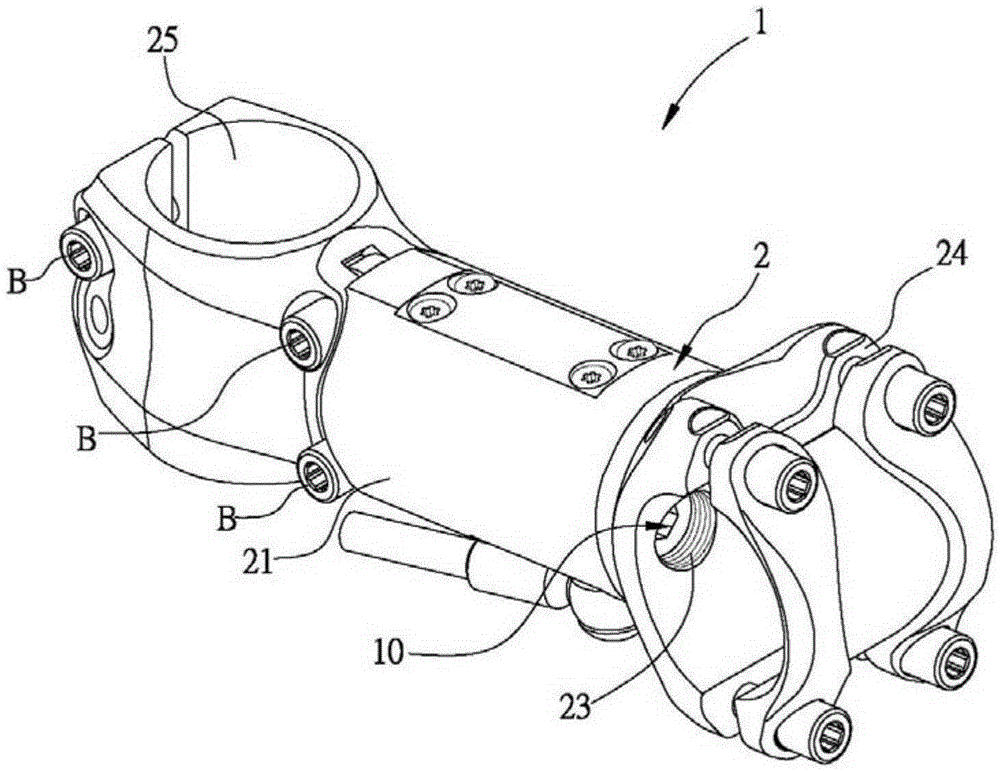
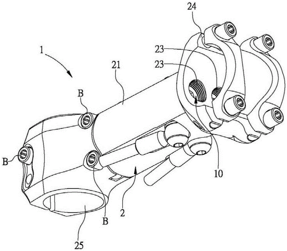
[0032] In order to describe the technical content, achieved goals and effects of the present invention in detail, the following descriptions will be made in conjunction with the embodiments and accompanying drawings.

[0033] figure 1 It is an exploded schematic view of the faucet hydraulic brake device of the present invention. figure 2 It is a schematic top view of the faucet hydraulic brake device of the present invention. image 3 It is a schematic bottom view of the faucet hydraulic brake device of the present invention. Figure 4 It is a schematic cross-sectional view of the faucet hydraulic brake device of the present invention. Figure 5 It is a schematic diagram showing that the faucet hydraulic brake device of the present invention is connected to the faucet handle and the front fork. Figure 6 It is a schematic diagram of adjusting the angle of the faucet hydraulic brake device of the present invention. Figure 7 It is a schematic diagram of a second embodiment...


PUM


Abstract

The invention discloses a faucet oil pressure brake device. A movable sleeve is rotated through an exposed outer protruding ring so that the end, away from the outer protruding ring, of the movable sleeve can get away from or abut against a first inner flange, the position of one of two-way through holes is adjusted, and use of a brake cannot be affected by the pressure of oil and air in a main oil cylinder. Then, two elastic sheets of an inner connecting piece are plugged in an inner conic portion, the outer protruding ring between the two ends of the inner connecting piece abuts against the portion, close to a fifth threaded portion, of a third inner flange, the two elastic sheets are squeezed by the inner conic portion to fixedly penetrate an end plug, a second piston and a first piston to one end of a brake cable at the portion of the two elastic sheets, and an intermediate pulling structure is formed. Therefore, the first piston is moved through the brake cable to adjust the oil pressure, and the position of a brake master cylinder can be adjusted according to the requirements of a user.

Description

technical field [0001] The invention relates to a bicycle related field, in particular to a faucet hydraulic brake device. Background technique [0002] By the way, the hydraulic brake device used in bicycles should be regarded as one of the most commonly used hydraulic devices. It is mainly equipped with a brake master cylinder driven by the brake handle at the handshake, and is connected to the corresponding device through a hydraulic pipeline. The brake caliper at the wheel; when the rider presses the brake handle, the handle drives a piston in the master cylinder of the brake master cylinder to move forward, pushing the hydraulic oil in the master cylinder into the auxiliary cylinder of the brake caliper, Make the brake pad at the auxiliary oil cylinder move toward the direction of the brake disc, use the brake pad to contact the brake disc on the wheel hub, and then generate a detent action on the wheel. [0003] However, the brake master cylinder is too bulky to match...

Claims


Application Information

Patent Timeline
Patent Type & Authority Applications(China)
IPC IPC(8): B62L3/02
Inventor 黄育铭
Owner TEKTRO TECH
Why Eureka
Try Eureka