High-speed controllable telescopic wing

A telescopic and telescopic wing technology, which is applied in wing adjustment, aircraft parts, aircraft control, etc., can solve the problems of telescopic speed and vibration, low transmission efficiency of transmission mechanism, and bulky telescopic wings, etc., to achieve stability Enhanced performance, easy to popularize and use, and improve the efficiency of aircraft orbit and speed change

Active Publication Date: 2017-05-10
XIAN UNIV OF SCI & TECH
View PDF3 Cites 5 Cited by
  • Summary
  • Abstract
  • Description
  • Claims
  • Application Information

AI Technical Summary

Problems solved by technology

In the existing published technical literature "Structure Design and Vibration Experimental Research of Scalable Wing", the structure design, function realization and vibration experiment of a retractable wing experimental device are studied, and the three-dimensional modeling software is used to optimize the design of the The actuating mechanism of the retractable wing completes the overall design of the retractable wing structure and the structural design of each subsystem, and analyzes in detail the lateral vibration response of the retractable wing under different extension and retraction speeds, but The implementation process is cumbersome, the designed retractable wing is relatively heavy, and the resistance suffered during the expansion and contraction process is too large, which has a great impact on the speed and vibration of the expansion and contraction; in addition, most of the existing retractable wings The design of the wing adopts the method of placing part of the transmission mechanism outside, which effectively reduces the installation space requirements of the wing for the internal mechanism. It is driven by a hydraulic telescopic rod, and the telescopic rod is placed outside. The transmission efficiency of this transmission mechanism is relatively small. , the transmission speed is relatively slow, it is difficult to stretch and deform in a very short time

Method used


Image

  • High-speed controllable telescopic wing
  • High-speed controllable telescopic wing
  • High-speed controllable telescopic wing

Examples


Embodiment Construction

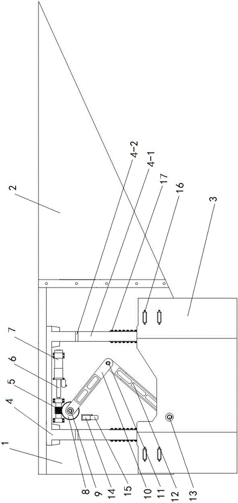
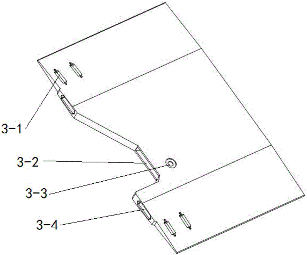
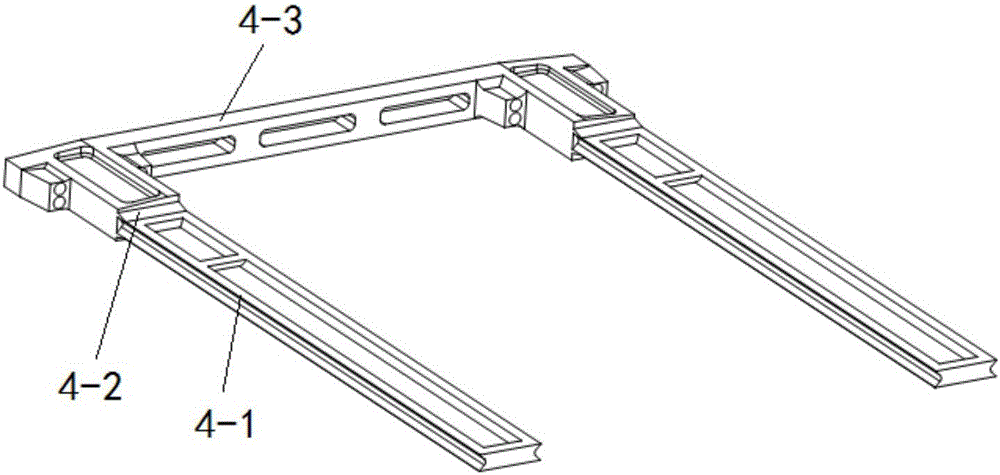
[0031] Such as figure 1 , figure 2 and image 3 As shown, the present invention comprises the fixed wing that is installed on the same side of the aircraft and the fixed wing aileron 2 that is connected with the fixed wing, and the telescopic wing 3 that expands and contracts along the extension direction of the fixed wing can be accommodated in the fixed wing, and the The fixed wing includes a fixed wing upper wing plate and a fixed wing lower wing plate 1, and the fixed wing lower wing plate 1 is equipped with a support bracket 4 for the sliding of the telescopic wing 3 and a transmission mechanism connected with the telescopic wing 3 and used to control the telescopic distance of the telescopic wing 3 , and the limit block 14 used to limit the position of the transmission mechanism, the end of the telescopic wing 3 facing the body is provided with a groove 3-2, a connecting hole 3-3 and two chute 3-4 arranged in parallel, telescopic One end of the wing 3 facing away from...


PUM


Abstract

The invention discloses a high-speed controllable telescopic wing. The high-speed controllable telescopic wing comprises a fixed wing and a fixed wing aileron which are positioned on the same side of an airplane, wherein the fixed wing can accommodate a telescopic wing which extends and retracts along the extension direction of the fixed wing; the fixed wing comprises a fixed wing upper wing plate and a fixed wing lower wing plate; a support bracket, a transmission mechanism and a limiting block are arranged on the fixed wing lower wing plate; one end, which faces an airplane body, of the telescopic wing is provided with a groove, a connecting hole and two parallel sliding chutes; one end, which is back to the airplane body, of the telescopic wing is enclosed; the support bracket comprises a connecting beam and two cantilever beams; buffering structures are arranged on joints between the cantilever beams and the connecting beam; sliding mechanisms are arranged on both sides of the cantilever beams respectively; the transmission mechanism comprises a worm wheel, a worm, a motor and a push-pull rod. The telescopic wing can be controlled to extend and retract rapidly; when the telescopic wing extends outwards, additional lifting force can be provided to enhance the flying stability; when the telescopic wing retracts, the stressed area of the wing can be reduced, the flexibility of the wing is enhanced, and the orbital transfer and speed change efficiency of an aircraft is increased.

Description

technical field [0001] The invention belongs to the technical field of telescopic wings, and in particular relates to a high-speed controllable telescopic wing. Background technique [0002] The deformable aircraft can change its shape according to the needs of navigation, so as to obtain the best performance in different flight states, and improve the multi-environment and multi-task adaptability of the aircraft. In the existing published technical literature "Structure Design and Vibration Experimental Research of Stretchable Wing", the structure design, function realization and vibration experiment of a stretchable wing experimental device are studied, and the 3D modeling software is used to optimize the design of the The actuating mechanism of the retractable wing completes the overall design of the retractable wing structure and the structural design of each subsystem, and analyzes in detail the lateral vibration response of the retractable wing under different extensio...

Claims


Application Information

Patent Timeline
Patent Type & Authority Applications(China)
IPC IPC(8): B64C3/54B64C5/18B64C13/24
CPCB64C3/54B64C5/18B64C13/24
Inventor 张传伟张腾党蒙
Owner XIAN UNIV OF SCI & TECH
Why Eureka
Try Eureka