An automatic throwing cylinder device

A cylindrical and automatic technology, which is applied to launch devices, motor vehicles, transportation and packaging, etc., can solve the problems of heavy structural weight and low delivery accuracy, and achieve the effects of easy installation and disassembly, high precision, and efficient and reliable delivery.

Active Publication Date: 2018-09-21
CHANGCHUN INST OF OPTICS FINE MECHANICS & PHYSICS CHINESE ACAD OF SCI
View PDF5 Cites 0 Cited by
  • Summary
  • Abstract
  • Description
  • Claims
  • Application Information

AI Technical Summary

Problems solved by technology

[0004] The purpose of the present invention is to propose an automatic cylinder throwing device to solve the problems of heavy structural weight and low throwing accuracy existing in the prior art

Method used


Image

  • An automatic throwing cylinder device
  • An automatic throwing cylinder device
  • An automatic throwing cylinder device

Examples


Embodiment Construction

[0024] Embodiments of the present invention will be further described below in conjunction with the accompanying drawings.

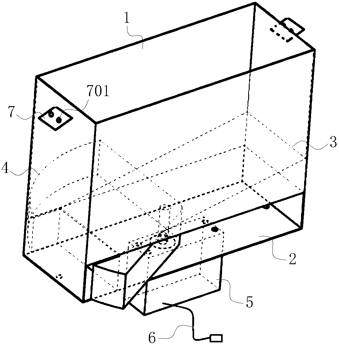
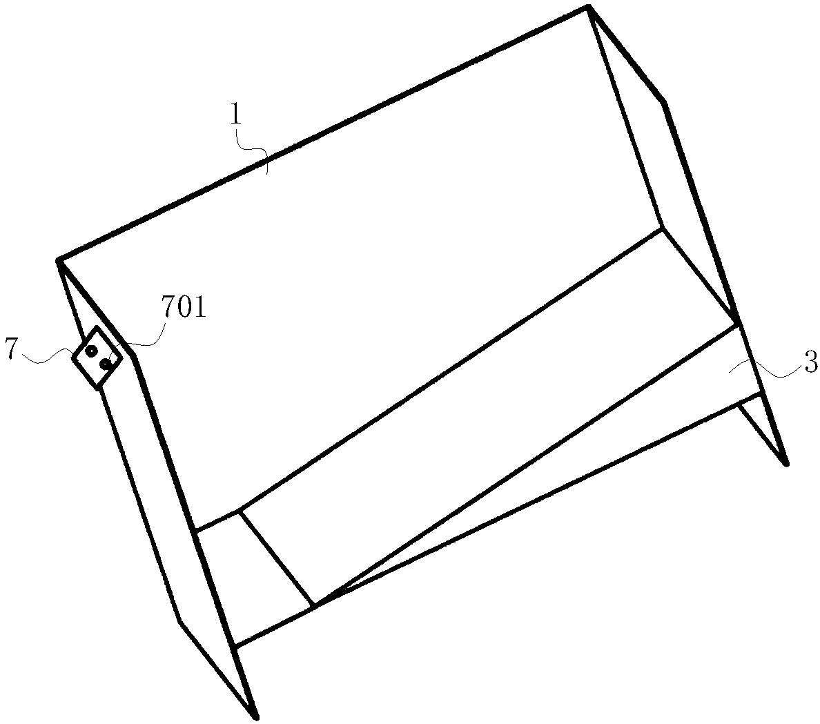
[0025] See attached figure 1 - attached figure 2 , a kind of automatic throwing cylinder device of the present invention comprises:

[0026] Hollow carrying body 1;

[0027] a fixed plate 2 fixed on the bottom of the bearing body 1;

[0028] An inclined plate 3 arranged in the carrying body 1 and fixed in contact with the inner wall of the carrying body 1;

[0029] The motion throwing baffle 4 of fan-shaped structure is arranged between the fixed plate 2 and the inclined plate 3, and the circular arc of the motion throwing baffle 4 has a groove 401 inwardly. At the beginning, the groove 401, fixed The upper end surface of the plate 2 and the side wall of the carrying body 1 form a cuboid hole, which is used to store the cylindrical container loaded with biological agents. The groove 401 and the fixed plate 2 are completely staggered, and the cylind...


PUM


Abstract

An automatic cylindrical injection device belongs to the technical field of biological agent injection, and aims to solve the problems of heavy structure weight and low injection accuracy existing in the prior art. The invention comprises: a hollow carrying body; a fixed plate fixed at the bottom of the carrying body; an inclined plate arranged in the carrying body and fixed in contact with the inner wall of the carrying body; a fan-shaped motion release baffle arranged between the fixed plate and the inclined plate There is a groove inward at the circular arc of the motion release baffle. Initially, the groove, the upper end surface of the fixed plate and the side wall of the bearing body form a cuboid hole, and the two ends of the arc structure of the motion release baffle protrude from the bearing body. When throwing, the groove and the fixed plate are completely staggered, and the cylindrical container in the cuboid hole falls; and the steering gear with the steering gear signal line is fixed at the lower end of the fixed plate, and the rotation axis of the steering gear passes through the fixed plate and the motion release gear The central position of the plate is fixedly connected, and the steering gear drives the motion release baffle to rotate after receiving the control signal through the steering gear signal line.

Description

technical field [0001] The invention belongs to the technical field of biological agent injection, and in particular relates to an automatic cylinder injection device installed on a multi-rotor aircraft and can be installed in a cylinder container. Background technique [0002] With the continuous progress and development of machinery, mechanics, control technology and other fields, multi-rotor UAVs have been widely used in public security, military and agriculture due to their simple structure, easy operation and high reliability. Wide range of applications. One of the important fields of application is the spreading of agricultural biological agents such as Trichogramma. The use of biological agents for ecological pest control not only solves the problem of toxic residues of chemical drugs and environmental pollution, but also has high control efficiency and low price and cost. Due to the high efficiency of biological agents, the amount of spreading per unit area is rela...

Claims


Application Information

Patent Timeline
Patent Type & Authority Patents(China)
IPC IPC(8): B64D1/12B64C27/08A01M99/00
CPCA01M99/00B64C27/08B64D1/12
Inventor 白越纪婷婷田久彰
Owner CHANGCHUN INST OF OPTICS FINE MECHANICS & PHYSICS CHINESE ACAD OF SCI
Why Eureka
Try Eureka