Waste compaction device and back-loaded compaction type waste truck

A technology of garbage compression and back door, applied in the direction of garbage storage, transportation and packaging, can solve the problems of reducing the garbage carrying space of the collection box, the compression stroke limit of the compression mechanism, and the small garbage carrying capacity of the collection box, etc. Transshipment costs, improving compression efficiency, and the effect of improving garbage compression efficiency

Active Publication Date: 2017-05-10
XIAMEN YULONG MACHINERY
View PDF12 Cites 1 Cited by
  • Summary
  • Abstract
  • Description
  • Claims
  • Application Information

AI Technical Summary

Problems solved by technology

However, in the current garbage collection box with a compression mechanism, the oil cylinder in the compression mechanism needs to be placed in the box, and the oil cylinder will take up a large part of the space in the collection box, reducing the effective garbage carrying space in the collection box, and the compression mechanism. The compression stroke will be limited, so the compression efficiency of garbage is low, and the garbage carrying capacity of the collection box is small, which incr...

Method used


Image

  • Waste compaction device and back-loaded compaction type waste truck
  • Waste compaction device and back-loaded compaction type waste truck
  • Waste compaction device and back-loaded compaction type waste truck

Examples


Embodiment Construction

[0026] The present invention will be described in further detail below in conjunction with the accompanying drawings and specific embodiments.

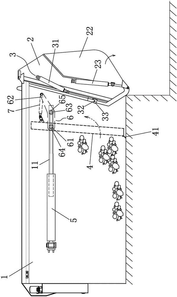
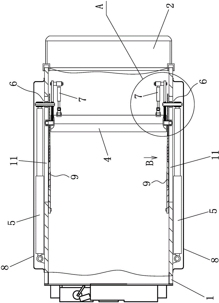
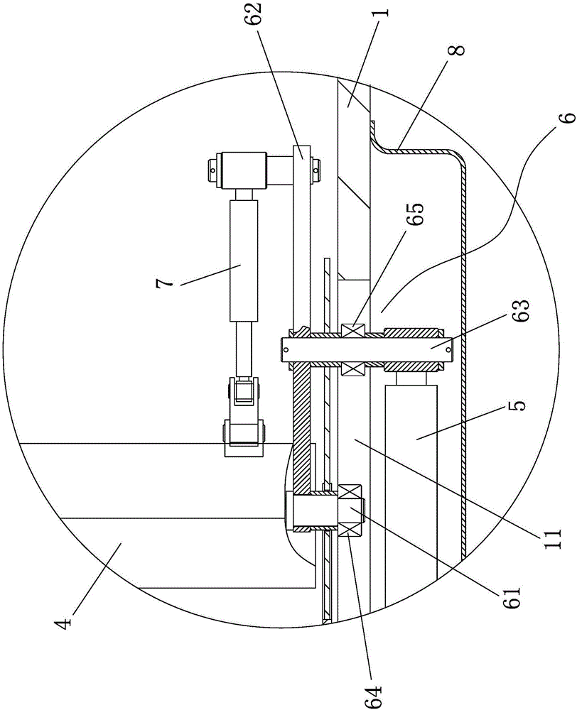
[0027] Figure 1 to Figure 5 As shown, a garbage compression device includes a box body 1, a back door 2 is hinged at the rear of the box body 1, a back door opening or closing mechanism 3 is installed between the back door 2 and the box body 1, and a garbage feeding mechanism 3 is arranged on the back door 2. Port 21, the box body 1 is equipped with a push plate 4, and the two outer sides of the box body 1 are symmetrically equipped with two driving parts. The driving part is preferably a push-pull oil cylinder 5. The components of the driving force; two sides of the box 1 corresponding to the two push-pull cylinders 5 are provided with two strip-shaped transverse through holes 11; each strip-shaped transverse through-hole 11 is equipped with a moving assembly 6, and the moving assembly 6 The outer side is connected with the push-pu...


PUM


Abstract

The invention discloses a waste compaction device which comprises a box body. A rear door is hinged to the rear portion of the box body. A waste inlet is formed in the rear door. A push plate is arranged in the box body. Two driving parts are symmetrically installed on the two outer side faces of the box body. Long-strip-shaped transverse through holes are formed in the positions, corresponding to the driving parts, of the two side faces of the box body. Each long-strip-shaped through hole is provided with a moving assembly. The outer sides of the moving assemblies are connected with the driving parts, the driving parts drive the moving assemblies to move along the long-strip-shaped transverse through holes, the inner sides of the moving assemblies and the side face of the push plate are hinged through first pin shafts, a rotating oil cylinder is installed between the inner side of each moving assembly and the rear side of the push plate, one end of each rotating oil cylinder is hinged to the inner side of the corresponding moving assembly, the other end of each rotating oil cylinder is hinged to the rear side of the push plate, and the push plate can be driven to rotate along the first pin shafts when the rotating oil cylinders act. By means of the waste compaction device, the waste bearing space can be enlarged, and the waste collection capacity of the box body can be improved. The invention further provides a back-loaded compaction type waste truck. The back-loaded compaction type waste truck comprises an automobile chassis. The automobile chassis is provided with the waste compaction device.

Description

technical field [0001] The invention relates to the technical field of garbage compression equipment manufacturing, in particular to a garbage compression device and a rear-mounted compression garbage truck. Background technique [0002] Due to problems such as odor and garbage seepage generated by the garbage transfer station or cleaning building, it will cause secondary pollution to the environment. Therefore, the direct transportation system of urban waste has formed a trend. This requires that the garbage collection box should be equipped with a compression mechanism, so that the garbage can be directly pulled to the disposal site after being compressed at the garbage collection site. However, in the current garbage collection box with a compression mechanism, the oil cylinder in the compression mechanism needs to be placed in the box, and the oil cylinder will take up a large part of the space in the collection box, reducing the effective garbage carrying space in the ...

Claims


Application Information

Patent Timeline
IPC IPC(8): B65F3/14B65F3/26
CPCB65F3/14B65F3/26
Inventor 李振营陈卿雁廖德峰
Owner XIAMEN YULONG MACHINERY
Why Eureka
Try Eureka