
Suction cup device for grabbing glass from lower surface of glass plate and control method

A glass plate and suction cup technology, used in transportation and packaging, conveyor objects, furnaces, etc., can solve problems affecting coating quality, glass impact, glass surface scratches, etc.

Pending Publication Date: 2017-05-10
CHINA TRIUMPH INT ENG
View PDF12 Cites 1 Cited by
  • Summary
  • Abstract
  • Description
  • Claims
  • Application Information

AI Technical Summary

Problems solved by technology

Since the LOW-E glass is coated on the air surface of the glass, if the glass is picked up by the traditional method of picking up the glass, the suction cup will be left on the glass surface, which will affect the coating quality. Therefore, the unloading of the original coated glass and the coated finished product film, it is necessary to use the method of picking up the glass to grab the glass
[0004] The existing stacker for unloading sheets is generally reformed from the deep-processing loading table. The suction cup is installed on the horizontal connecting rod, and the up and down of the suction cup is realized by the swing of the swing rod. There is relative sliding between them, which may easily cause scratches on the glass surface
There is also a structure in which the suction cup is directly installed on the cylinder, and there is also a type of unloading stacker. Although the suction cup does not slide between the glass, there is no buffer between the suction cup and the glass, and the glass is easy to be damaged during the lifting process of the suction cup. cause shock
[0005] And at present there is not a kind of sucker device that can solve the above problems to grab glass from the lower surface of the glass plate

Method used


Image

  • Suction cup device for grabbing glass from lower surface of glass plate and control method
  • Suction cup device for grabbing glass from lower surface of glass plate and control method
  • Suction cup device for grabbing glass from lower surface of glass plate and control method

Examples


Embodiment Construction

[0029] In order to better clearly express the technical solution of the present invention, the present invention will be further described below in conjunction with the accompanying drawings.

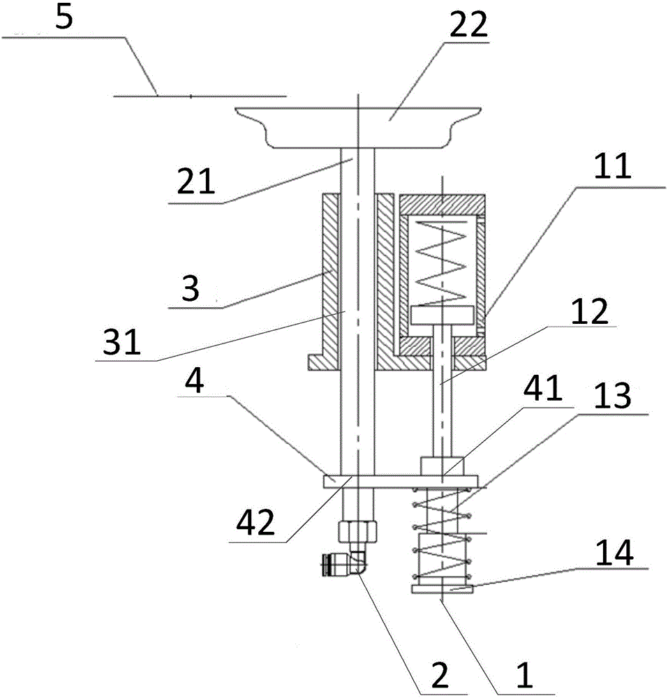
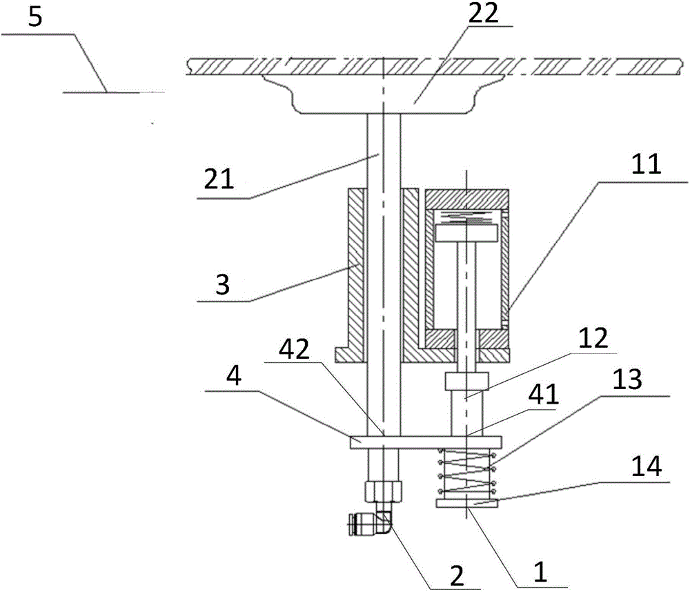
[0030] figure 1 It shows a specific embodiment of the present invention, in the initial state of work, a schematic structural view of a suction cup device for grabbing glass from the lower surface of a glass plate, and as a first embodiment of the present invention, figure 2 Showing the first embodiment of the present invention, in the working state, a schematic structural view of a sucker device for grabbing glass from the lower surface of a glass plate, those skilled in the art understand that the present invention will combine Figure 1 to Figure 2 To further describe the internal structure and connection relationship of the suction cup device, for a better understanding of the present invention, figure 1 as well as figure 2 The dynamics and working principle of the suction cup s...


PUM


Abstract

The invention provides a suction cup device for grabbing glass from the lower surface of a glass plate. The device at least comprises a driving portion, a driven portion and an installation base. The driving portion is connected with the driven portion through a connecting plate. The installation base is connected with the driving portion. The driving portion comprises a cylinder, a cylinder rod, a buffer spring and a buffer support which are sequentially arranged from top to bottom. The installation base wraps the cylinder. A first hole is formed in the connecting plate. The upper end of the cylinder rod is connected with the bottom of the cylinder and stretches out from the lower portion of the installation base, and penetrates through the first hole to be sequentially connected with the buffer spring and the buffer support. A second hole is formed in the connecting plate. The driven portion comprises a perpendicularly-arranged suction cup rod. The suction cup rod penetrates through the second hole to be fixedly connected. A suction cup is arranged above the suction cup rod. The suction cup device is simple in structure, convenient to use and obvious in buffer effect and has quite high commercial value.

Description

technical field [0001] This patent belongs to the field of glass machinery, in particular to a sucker device for grabbing glass from the lower surface of a glass plate. Background technique [0002] Glass is an indispensable item in our life, and its production needs to go through many processes. For example, after the float glass is cut, it needs to be transported to the end of the production line through the conveying roller table, and the glass is removed from the roller table using a stacker. Remove the stacking package, and the traditional stacker uses the method of picking up the glass on the suction cup. [0003] In recent years, with the development of science and technology and the enhancement of human environmental awareness, LOW-E coated glass has been used more and more in the field of construction. Since the LOW-E glass is coated on the air surface of the glass, if the glass is picked up by the traditional method of picking up the glass, the suction cup will be...

Claims


Application Information

Patent Timeline
IPC IPC(8): B65G49/06
CPCB65G49/061
Inventor 程明张仰平杨培广刘锐姚亮亮
Owner CHINA TRIUMPH INT ENG
Learn More