Hoisting type opening and closing machine

A hoist and winch-type technology, which is applied in the direction of hoisting devices and clockwork mechanisms, can solve the problems of easy dust absorption, agglomeration, poor lifting movement, etc., and achieves compact structure and good use stability , good dustproof effect

Active Publication Date: 2017-05-10
THE JIANGSU GENERAL FACTORY OF WATER CONSERVANCY MACHINERY
View PDF8 Cites 2 Cited by
  • Summary
  • Abstract
  • Description
  • Claims
  • Application Information

AI Technical Summary

Problems solved by technology

Yet people find in actual use, because the wire rope that is wound on the winch is exposed outside for a long time, therefore, very easily absorbs dust on the wire rope surface and coagulates into agglomerate, thereby brings the normal use of wire rope great influence
[0003] In addition, since both ends of the wire rope are fixed on the surface of the winch, once the wire rope is wound unevenly, great resistance will be generated in the process of retracting and unwinding the wire rope, making its final lifting movement It becomes extremely unsmooth, which greatly affects the use effect and work efficiency of the winch hoist

Method used


Image

  • Hoisting type opening and closing machine
  • Hoisting type opening and closing machine
  • Hoisting type opening and closing machine

Examples


Embodiment 1

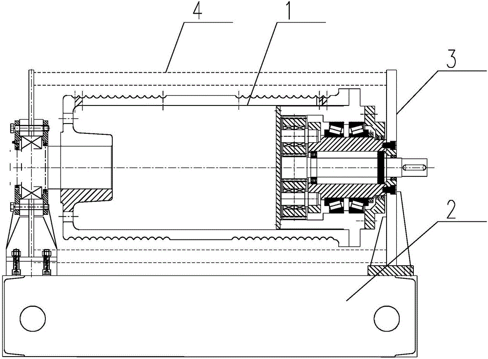
[0048] Embodiment one, such as Figure 4-11 As shown: the forward rotation drive system 53 includes driving gear 1 531, driven gear 1 532, transmission key 1 533, push rod 1 534, pull rod 1 535, combined spring 1 536 and separation spring 1 537, the driving gear A 531 is fixedly connected to one side of the hoisting drum 1 and is coaxial with the hoisting drum 1, the driven gear 1 532 is sleeved on the main shaft 51, and is linked with the driving gear 1 531 through a synchronous belt;

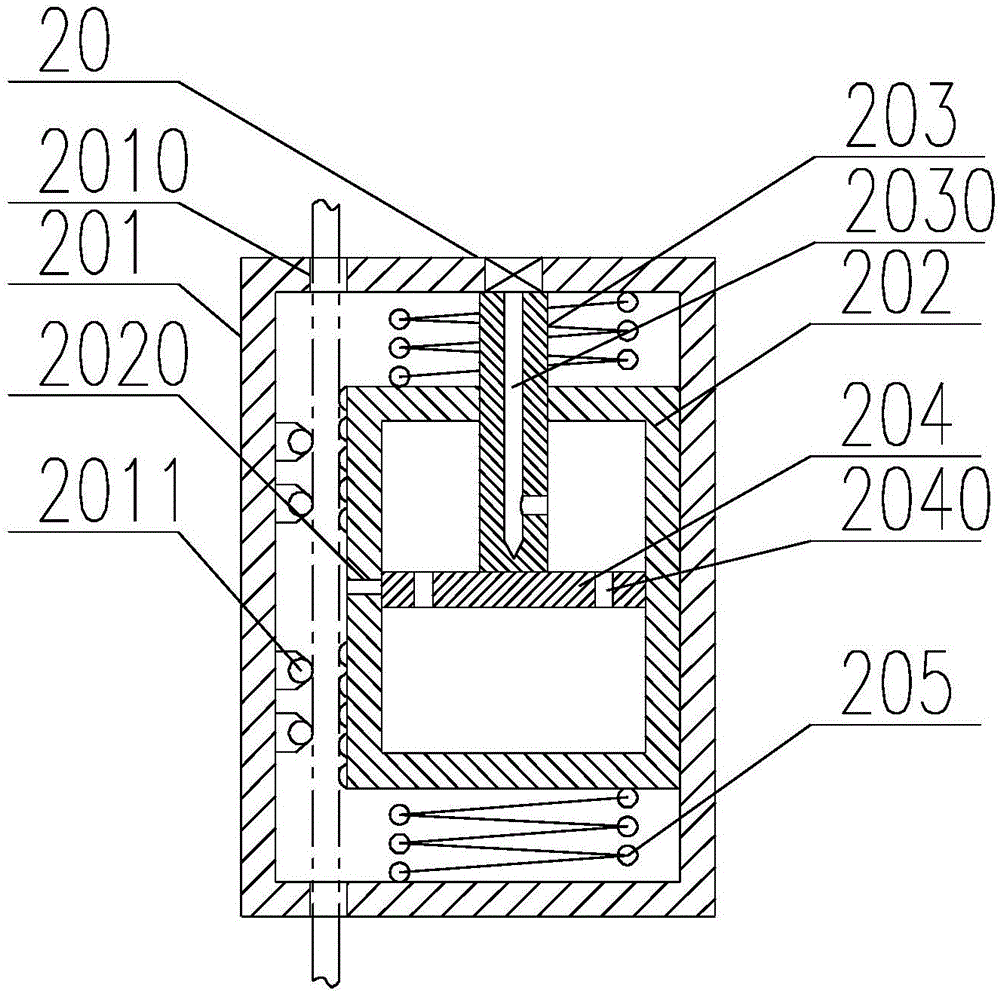
[0049] The main shaft 51 is provided with a chute one 511 located inside the driven gear one 532 and longer than the transmission key one 533, and the lower part of the transmission key one 533 is slidingly connected (a T-shaped, dovetail-shaped sliding structure can be used to Avoid driving key 1 from being thrown out when not combined with driven gear 1) In the chute 1 511, the inner edge of the driven gear 1 532 facing away from the center of the main shaft 51 is provided with a plug compat...

Embodiment 2

[0061] Embodiment two, such as Figure 12-13 As shown: the forward rotation drive system 53 includes a forward rotation motor 538 and a pair of forward rotation trigger blocks 539, and the two forward rotation trigger blocks 539 are fixedly connected to the base 2 and located between two sections of external threads. The forward rotation motor 538 is fixedly connected to the base 2 and detachably connected to the main shaft 51;

[0062] The reverse drive system 54 includes a reverse motor 548 and a pair of reverse trigger blocks 549. The two reverse trigger blocks 549 are fixedly connected to the base 2 and are located outside the two sections of external threads. The reverse motor 548 is fixedly connected to the base 2 and is detachably connected to the main shaft 51;

[0063] The forward rotation motor 538 and the reverse rotation motor 548 are respectively arranged on two sides of the main shaft 51 . When the main shaft rotates forward, the two wiring boards move from ins...


PUM


Abstract

The invention provides a hoisting type opening and closing machine, relates to the field of machinery equipment and particularly relates to improvement of the hoisting type opening and closing machine. The hoisting type opening and closing machine provided by the invention has the advantages of ingenious structure, good dustproof effect, good utilization stability and high movement efficiency in a utilization process. The hoisting type opening and closing machine comprises a hoisting barrel, a base and a pair of fixed plates; the pair of fixed plates are fixedly connected onto the base; the hoisting barrel is hinged between the two fixed plates; and a dustproof cover, which covers the hoisting barrel, is further fixedly connected between the two fixed plate. A pull rod II is C-shaped and the middle part of the pull rod II is in sliding connection with the base; one end of the pull rod II is located at one side, toward the center of a main shaft, of a driven gear II; and the other end of the pull rod II is located on one side, back to the center of the main shaft, of a separation spring II. The hoisting type opening and closing machine wholly has the characteristics of ingenious structure, good dustproof effect and good utilization stability.

Description

technical field [0001] The invention relates to the field of mechanical equipment, in particular to the improvement of the hoist hoist. Background technique [0002] The hoist hoist usually uses steel cables or cable pulley blocks as the spreader, and uses a gear transmission system to wind the hoist drum and put the steel cables to drive the mechanical equipment of the workpiece. Yet people find in actual use, because the wire rope that is wound on the winch is exposed outside for a long time, therefore, very easily absorbs dust on the wire rope surface and coagulates into agglomerate, thereby brings the normal use of wire rope huge impact. [0003] In addition, since both ends of the wire rope are fixed on the surface of the winch, once the wire rope is wound unevenly, great resistance will be generated in the process of retracting and unwinding the wire rope, making its final lifting movement It becomes extremely unsmooth, which greatly affects the use effect and work e...

Claims


Application Information

Patent Timeline
Patent Type & Authority Applications(China)
IPC IPC(8): B66D1/30B66D1/28B66D1/14B66D1/12
CPCB66D1/12B66D1/14B66D1/28B66D1/30B66D2700/0183
Inventor 王波钟卫华田建京陈照李学荣蒋平陈军郑殿东任菲菲郑春峰孙永明单凤军陈家强曾亚玲陆海翔
Owner THE JIANGSU GENERAL FACTORY OF WATER CONSERVANCY MACHINERY
Why Eureka
Try Eureka