Integrated bridge abutment structure for controlling earth pressure behind abutment and filled earth settlement and construction method

An integral abutment and control console technology, which is applied to bridges, bridge parts, bridge construction, etc., can solve the problems of increasing bridge maintenance costs, reducing the flatness of road pavement, and bridge head jumping, etc. Bearing capacity, maintaining beauty and tidiness, and preventing road surface damage

Inactive Publication Date: 2017-05-10
FUZHOU UNIV
View PDF6 Cites 3 Cited by
  • Summary
  • Abstract
  • Description
  • Claims
  • Application Information

AI Technical Summary

Problems solved by technology

[0002] With the continuous development of engineering technology in our country, the integral abutment seamless bridge is favored by engineers because of its many advantages. The integral bridge can effectively avoid setting expansion joints and supports, increase the driving quality, and has good integrity and seismic performance. It reduces the later maintenance, saves the life cycle cost of the bridge, and simplifies the construction method; however, because it cancels the expansion joint device and is directly cast in place with the bridge head strapping plate, it is difficult to avoid temperature effects and concrete shrinkage and creep. Under the action of the displacement of the bridge deck, local deformation will occur between the abutment, the slab and the backfill, and the soil behind the abutment will settle under the action of the cyclic movement of the abutment, which will cause the soil under the slab to Empty, the upper slab (approach slab) of the emptied is extremely cracked under the combined load of vehicles, causing road cracks and bridge head jumping. A crack will reduce the flatness of the road pavement layer and affect the driving quality and increase bridge maintenance costs

Method used


Image

  • Integrated bridge abutment structure for controlling earth pressure behind abutment and filled earth settlement and construction method
  • Integrated bridge abutment structure for controlling earth pressure behind abutment and filled earth settlement and construction method
  • Integrated bridge abutment structure for controlling earth pressure behind abutment and filled earth settlement and construction method

Examples


Embodiment Construction

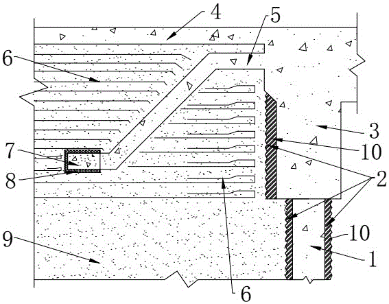
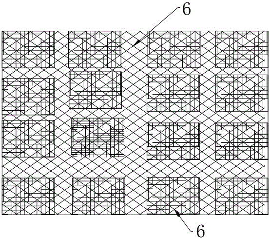
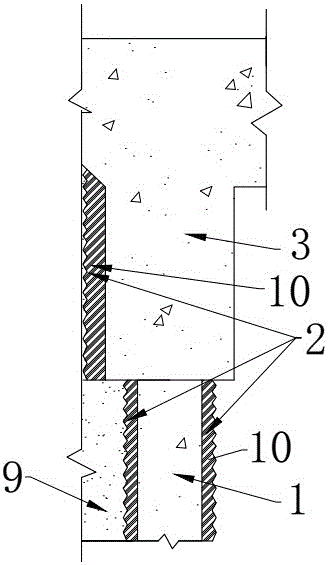
[0029] Such as figure 1 As shown in ~3, the embodiment of the present invention provides an integral abutment structure with earth pressure and filling settlement behind the control console, an integral abutment structure with earth pressure and filling settlement behind the control console, including the abutment body And the anti-Z-shaped butting plate connected with the abutment body, the upper and lower sides of the said butting plate are respectively vertically laid with an upper filling layer and a lower filling layer reinforced by several layers of geogrids. The upper filling layer is extended upwards to the road surface, and the lower filling layer is extended downwards to the foundation; a first gap; the end of the horizontal end of the butt plate is open and rigidly connected to the abutment body; the end of the lower horizontal end of the butt plate is sealed by a rectangular steel sleeve, and the rectangular steel sleeve is horizontally sleeved on the butt plate ...


PUM


Abstract

The invention relates to an integrated bridge abutment structure for controlling earth pressure behind an abutment and filled earth settlement and a construction method. The integrated bridge abutment structure comprises an abutment body and a lapping plate, wherein an upper filled earth layer and a lower filled earth layer which are reinforced and firmed by a plurality of layers of geogrids are laid above and below the lapping plate respectively in the vertical direction, the upper filled earth layer upward extends to be laid on the road surface, and the lower filled earth layer downward extends to be laid on the abutment. A first gap is reserved between the upper filled earth layer and the lower filled earth layer and the surface of the lapping plate and the surface of the abutment body respectively. An end opening formed in the upper horizontal end of the lapping plate is in rigid connection with the abutment body. The end portion of the lower horizontal end of the lapping plate is sealed by a rectangular steel sleeve, a second gap is reserved between the inner side of the rectangular steel sleeve and the outer side of the lower horizontal end of the lapping plate and is filled with a rubber layer immersed with grease, and the outer surface of the rectangular steel sleeve is coated with an anticorrosive coating. The integrated bridge abutment structure utilizes good deformation of the lapping plate and reinforcement and firming of the geogrids, is good in integrity, improves pavement strength and effectively controls settlement behind the integrated bridge abutment.

Description

technical field [0001] The invention relates to an integral abutment structure and a construction method for earth pressure and filling settlement behind a console, and belongs to the technical field of bridges. Background technique [0002] With the continuous development of engineering technology in our country, the integral abutment seamless bridge is favored by engineers because of its many advantages. The integral bridge can effectively avoid setting expansion joints and supports, increase the driving quality, and has good integrity and seismic performance. It reduces the later maintenance, saves the life cycle cost of the bridge, and simplifies the construction method; however, because it cancels the expansion joint device and is directly cast in place with the bridge head strapping plate, it is difficult to avoid temperature effects and concrete shrinkage and creep. Under the action of the displacement of the bridge deck, local deformation will occur between the abutm...

Claims


Application Information

Patent Timeline
Patent Type & Authority Applications(China)
IPC IPC(8): E01D19/02E01D21/00E01C3/04
CPCE01C3/04E01D19/02E01D21/00
Inventor 庄一舟程俊峰黄福云林友炜
Owner FUZHOU UNIV
Why Eureka
Try Eureka