Sewage lifting system

A sewage lifting and sewage lifting pump technology, applied in waterway systems, water supply devices, drainage structures, etc., can solve problems such as failure to lift sewage, insufficient lifting force, and backflow pollution, so as to improve the efficiency of sewage extraction and avoid backflow pollution. , The effect of preventing the backflow of sewage

Inactive Publication Date: 2017-05-10
安顺汇景卫生材料科技有限公司
View PDF5 Cites 1 Cited by
  • Summary
  • Abstract
  • Description
  • Claims
  • Application Information

AI Technical Summary

Problems solved by technology

The current sewage lifting system is to use a sewage lifting pump to lift the sewage from the pipelines of each branch to the sewage main pipeline, and then send it to the sewage treatment equipment. This structure is simple, easy to operate and cost-saving. Insufficient, it is often necessary to add a spare pump. Although adding a spare pump increases the power to a certain extent and improves the extraction capacity, it still cannot effectively improve the pumping of sewage, and it is difficult to achieve the extraction effect.
Moreover, sewage backflow often occurs on branch pipelines when pumping is stopped, causing backflow pollution and failing to achieve the purpose of lifting sewage for treatment
In addition, there are no monitoring measures for each branch, resulting in no monitoring of the extraction volume. Which branch is working normally or malfunctioning, making the sewage lifting and extraction unable to proceed normally, affecting the efficiency of sewage treatment

Method used


Image

  • Sewage lifting system
  • Sewage lifting system

Examples


Embodiment Construction

[0010] The principles and features of the present invention are described below in conjunction with the accompanying drawings, and the examples given are only used to explain the invention, and are not intended to limit the scope of the present invention.

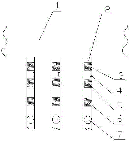
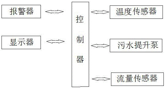
[0011] A sewage lifting system, including a sewage main pipeline 1, a sewage branch pipe 2, a flow sensor 3, a temperature sensor 4, a check valve 5, a butterfly valve 6, a sewage lifting pump 7, an alarm, a controller and a display, and the sewage main pipeline 1 flows to Sewage treatment equipment, one end of the sewage branch pipe 2 is connected to the sewage main pipe 1 and the other end is connected to the sewage source, the flow sensor 3 is arranged in the sewage branch pipe 2 and is located at the end of the sewage main pipe 1, and the temperature sensor 4 is arranged in the sewage branch pipe 2 and located at the end of the sewage main pipe 2. The back end of the flow sensor 3, the check valve 5 is set in the sewage ...


PUM


Abstract

The invention discloses a sewage lifting system. The sewage lifting system comprises a sewage main pipeline, sewage branch pipes, flow sensors, temperature sensors, check valves, butterfly valves, sewage lifting pumps, an alarm, a controller and a displayer, wherein the sewage main pipeline flows to a sewage treatment device; one end of each sewage branch pipe is connected with the sewage main pipeline, and the other end of each sewage branch pipe is connected with a sewage source; each flow sensor is arranged in each sewage branch pipe and is located at an end entering the sewage main pipeline; each check valve is arranged in each sewage branch pipe and is located at the rear end of each temperature sensor; each butterfly valve is arranged in each sewage branch pipe and is located at the rear end of each check valve; each sewage lifting pump is arranged in each sewage branch pipe and is located at the rear end of each butterfly valve; the alarm, the controller and the displayer are arranged in a control room; the flow sensors, the temperature sensors, the sewage lifting pumps, the alarm and the displayer are connected with the controller via a cable. The sewage lifting system is simple in structure and convenient to mount and maintain; each branch is specially provided with lifting power; the sewage in all the branches is effectively lifted to the sewage main pipeline; the sewage pumping efficiency is improved.

Description

technical field [0001] The invention relates to the technical field of sewage treatment, in particular to a sewage lifting system. Background technique [0002] Sewage lifting is to provide power for polluted wastewater, raise it to a height, and realize the purpose of sending sewage to a predetermined location for treatment, which can effectively solve or avoid the problems existing in traditional sumps, thereby reducing environmental pollution. The current sewage lifting system is to use a sewage lifting pump to lift the sewage from the pipelines of each branch to the sewage main pipeline, and then send it to the sewage treatment equipment. This structure is simple, easy to operate and cost-saving. If it is not enough, it is often necessary to add a spare pump. Although adding a spare pump increases the power to a certain extent and improves the extraction capacity, it still cannot effectively improve the sewage pumped out, and it is difficult to achieve the extraction eff...

Claims


Application Information

Patent Timeline
Patent Type & Authority Applications(China)
IPC IPC(8): E03F5/22
CPCE03F5/22E03F2201/20
Inventor 吴驰陈显发冯自云
Owner 安顺汇景卫生材料科技有限公司
Why Eureka
Try Eureka