Concrete pump with vibration type hopper fence

A concrete pump, vibrating technology, which is applied in the processing of building materials, earth-moving drilling, wellbore lining, etc., can solve the problems of low vibration frequency, low efficiency, and increase the maintenance cost of concrete pumps, so as to facilitate replacement and reduce production. cost effect

Inactive Publication Date: 2017-05-10
重庆华耀混凝土有限公司
View PDF9 Cites 2 Cited by
  • Summary
  • Abstract
  • Description
  • Claims
  • Application Information

AI Technical Summary

Problems solved by technology

This fence vibration method improves work efficiency and reduces potential safety hazards, but due to the need to add additional vibration sources and some additional accessories to the concrete pump, the cost of the concrete pump increases, which is not conducive to market promotion; and the concrete pump The working environment is harsh, and the newly added vibration source increases the failure points of the equipment to a certain extent, and its reliability is reduced; in addition, the space above the hopper fence is limited, which brings difficulties to the design of the concrete pump; Inconvenient maintenance, which in turn increases the maintenance cost of the concrete pump
Therefore, many of the above-mentioned shortcomings have led to domestic concrete pump manufacturers not using this mechanism, and still using the original manual method of removing concrete, which is time-consuming, laborious, and inefficient.
[0006] The concrete pump with the patent No. ZL201010127030.0 drives the fence to vibrate through the cam. However, this vibration is rigid and has a very large impact on the concrete pump, hopper, and fence, which will greatly reduce the service life of the concrete pump, hopper, and fence. Moreover, the frequency of this vibration is low, and the problem of concrete accumulation is still not completely solved

Method used


Image

  • Concrete pump with vibration type hopper fence
  • Concrete pump with vibration type hopper fence
  • Concrete pump with vibration type hopper fence

Examples


Embodiment Construction

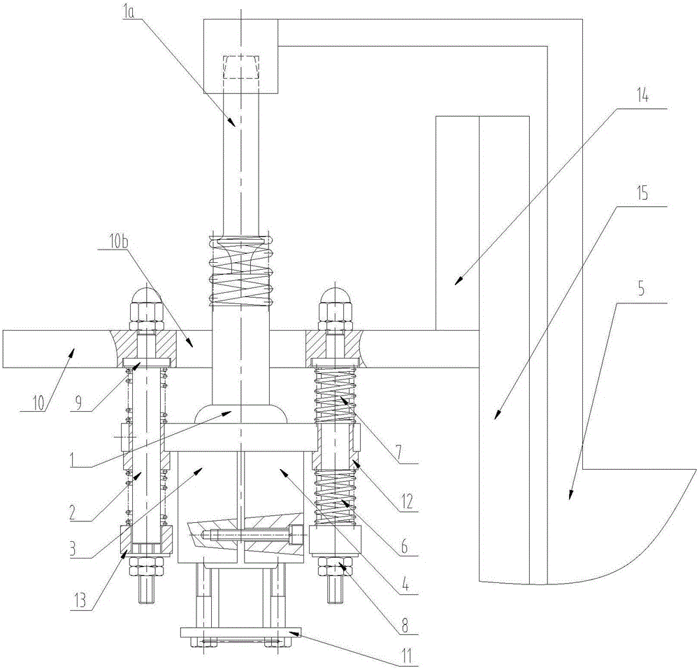
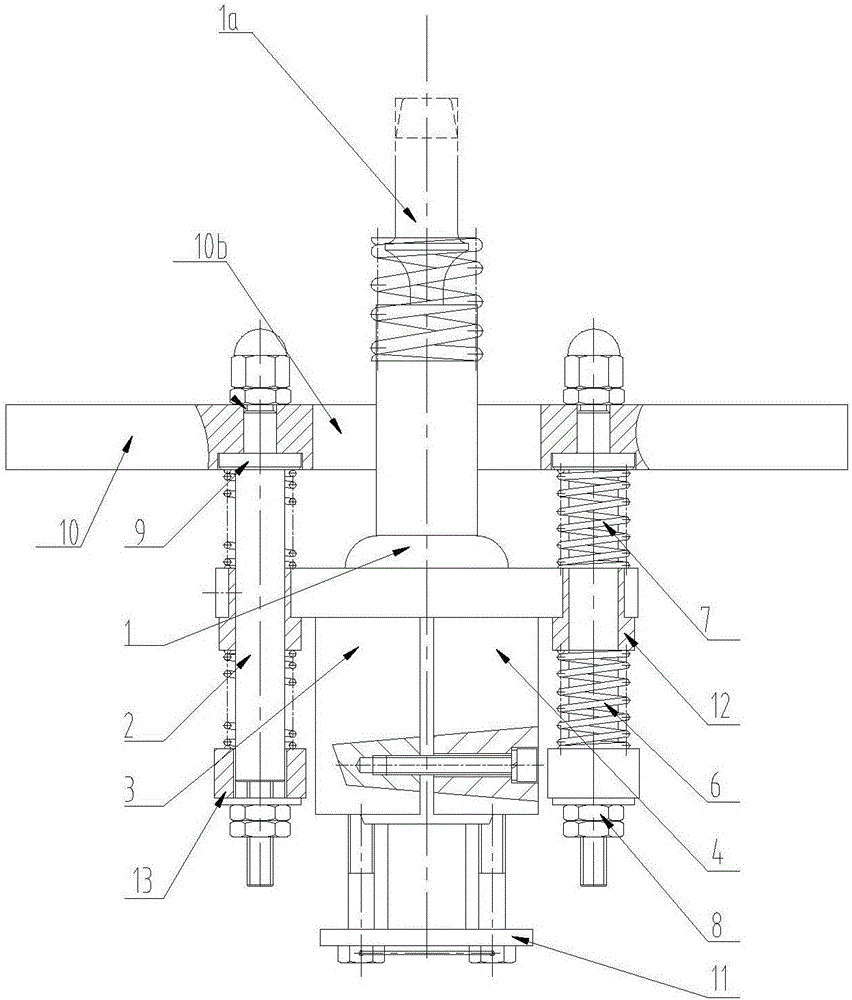
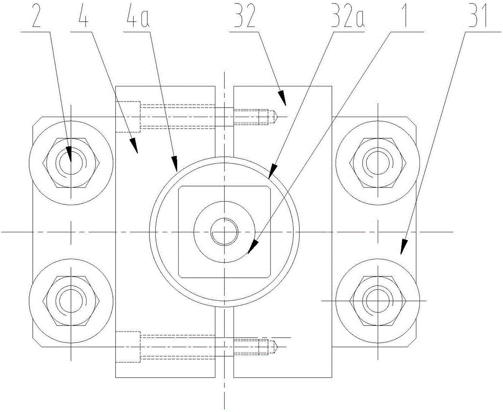
[0029] see Figure 1 to Figure 5, is a concrete pump with a vibrating hopper fence, comprising a concrete mixing device, a hopper and a fence arranged in the hopper, and a vibrating device for driving the fence, the vibrating device includes a pneumatic vibrator 1, A device for clamping a pneumatic vibrator, a guide rod 2, the device for clamping a pneumatic vibrator is composed of a clamping seat 3 and a clamp 4, and the clamping seat 3 includes a bottom plate 31 and a clamping base Seat 32, the bottom plate 31 is provided with a relief through hole 31a and a plurality of guide rod through holes 31b, the relief through hole 31a is located in the center between the plurality of guide rod through holes 31b, The seat 32 is fixed on the lower end surface of the base plate 31, and is located on one side of the through hole 31a. The clamping base 32 is provided with an arc groove 32a on the side facing the axis line of the through hole 31a. The arc groove 32a The center of the arc...


PUM


Abstract

The invention discloses a concrete pump with a vibration type hopper fence. By adoption of the concrete pump, the problem of concrete accumulation is thoroughly solved. The concrete pump comprises a concrete stirring device, a hopper, the fence and a vibration device which comprises a pneumatic vibrator, a device used for clamping the pneumatic vibrator, and guide rods. The device used for clamping the pneumatic vibrator comprises a base plate, a clamping base and clamp pincers. The base plate is provided with a receding through hole. The clamping base is fixed to the lower end face of the base plate. The clamping pincers are fastened to the clamping base through screws to fix the pneumatic vibrator. An impact rod of the pneumatic vibrator extends upwards to penetrate through the receding through hole to be connected with the fence. The base plate is provided with a plurality of guide rod passing holes to be slidably matched with the guide rods. The upper extending ends and the lower extending ends of all the guide rods are separately sleeved with upper and lower compression springs which are axially fixed. The upper ends of all the guide rods are connected to a connecting plate which is fixed to the hopper. A mounting plate is provided with a receding passing hole used for allowing the impact rod of the pneumatic vibrator to penetrate through and extend out.

Description

technical field [0001] The invention relates to the field of concrete machinery, in particular to a concrete pump with a vibrating hopper fence. Background technique [0002] Concrete pump is a kind of high-efficiency concrete conveying machinery, which is widely used in high-rise buildings, coal mines, mines, tunnels, railways, highways, bridges, ports, water conservancy, electric power, national defense projects and other concrete projects. It continuously presses the concrete to the pouring site through the pipeline, and has good maneuverability. [0003] When the concrete pump is pumping concrete, the concrete delivery tanker needs to continuously dump the concrete into the concrete pump hopper. In order to prevent large materials from entering the hopper and to ensure safe operation, a grid structure fence is generally designed on the upper surface of the hopper. The main The function is to prevent the excessive material in the concrete mortar from entering the hopper,...

Claims


Application Information

Patent Timeline
Patent Type & Authority Applications(China)
IPC IPC(8): E21D11/10E02D15/02E04G21/04
CPCE21D11/105E02D15/02E04G21/04
Inventor 曾华
Owner 重庆华耀混凝土有限公司
Why Eureka
Try Eureka