Check patentability & draft patents in minutes with Patsnap Eureka AI!

Axial flow force loose-leaf flow wheel

It is a fluid flow and loose-leaf technology, which is applied in the field of hydraulic flow wheels or turbines. It can solve the problems of unfavorable generators, unstable flow, flow channel hydraulics, tides, and ocean currents. It can improve the utilization value of slow flow and stabilize flow. Wheel or turbine power, the effect of balancing natural energy power

Inactive Publication Date: 2017-05-10
毛永波
View PDF0 Cites 3 Cited by
  • Summary
  • Abstract
  • Description
  • Claims
  • Application Information

AI Technical Summary

Problems solved by technology

[0004] The flow force in natural energy is very unstable, but the existing water wheels are all fixed propeller runners or turbines, which can only be left to their own devices. When the flow is rapid, the thrust is high and the speed is fast, and when the flow is slow, the thrust is low and the speed is slow. Turn, this is very unfavorable to the generator, and the power output is unstable, so the water power of the flow channel and the tide and ocean current have been neglected.

Method used


Image

  • Axial flow force loose-leaf flow wheel
  • Axial flow force loose-leaf flow wheel
  • Axial flow force loose-leaf flow wheel

Examples


Embodiment Construction

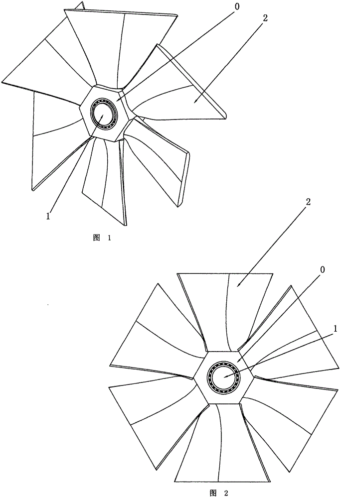
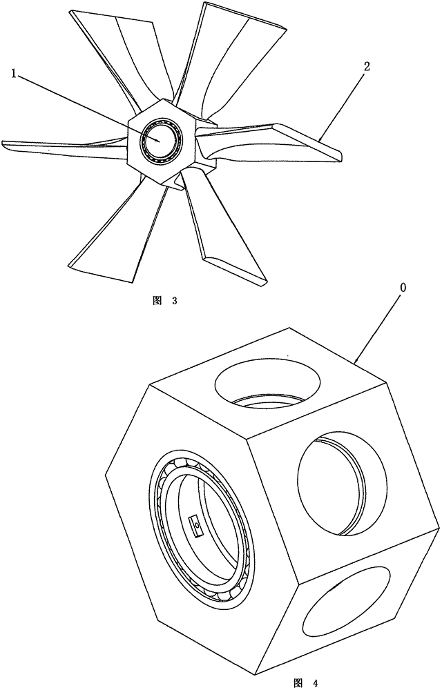
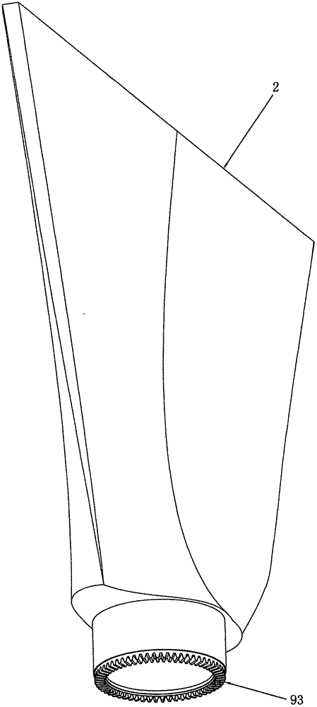
[0053] The axial flow loose-leaf runner, as shown in Figures 1, 2 and 3, includes: a hub 0, a loose-leaf 2 and a swing driver 7; the loose-leaf 2 surrounds the hub 0 in an axial annular array and is sleeved with a bearing at one end It is rotatably installed on the hub 0; the swing drive 7 is a component that drives the loose leaf 2 to rotate and swing, one end of which is connected to the hub 0 and the other end is connected to the loose leaf 2.

[0054] The axial flow loose-leaf flow wheel, as shown in Figures 10, 12, and 13, includes: a hub 0, a support rod 12, a loose leaf 2 and a swing drive member 7; the support rod 12 surrounds the hub 0 in an axial annular array And one end is fixed on the hub 0; the loose leaf 2 surrounds the hub 0 in an annular array and is sleeved with the support rod 12 to rotate and swing on the shaft; the swivel drive 7 is a component that drives the loose leaf 2 to rotate and swing, and its One end is connected to the hub 0 and the other end is con...


PUM


Abstract

The invention discloses an axial flow force loose-leaf flow wheel which comprises a hub, loose leaves, an outer wheel, a chain cable or a support rod, and a rotation and swinging driving part. According to the flow wheel, the traditional fixed propellers are replaced by the loose leaves, and the loose leaves are rotated and swung on the flow wheel by a pressure part or a tension part or a power unit, so that self-control variable flow scraping of the flow wheel or a turbine can be realized, the power of natural energy is balanced, the power of the flow wheel or the turbine is stabilized, and the utilization value of slow flow is improved.

Description

[0001] 【Technical Field】 [0002] The invention relates to hydraulic wind power equipment, especially hydraulic runners or turbines. [0003] 【Background technique】 [0004] The flow force in natural energy is very unstable, but the existing water wheels are all fixed propeller flow wheels or turbines, which can only be left as they are. The high thrust is high and the speed is fast in the rapid flow, and the small thrust is low and the speed is slow in the slow flow. This is very unfavorable to the generator, and the power output is unstable, so the flow channel hydraulic power and ocean tides and ocean currents have been left out. [0005] [Content of the invention] [0006] The purpose of the present invention is to realize the flow wheel or turbine self-control variable scraping, balance natural energy power, stabilize the flow wheel or turbine power, and improve the utilization value of slow flow. [0007] The invention utilizes the loose leaf to swing on the flow wheel, and uses th...

Claims


Application Information

Patent Timeline
IPC IPC(8): F03B3/12F03B3/14F03D1/06F03D1/02F03D7/02
CPCF03B3/123F03B3/14F03B3/145F03D1/025F03D1/0633F03D1/065F03D7/0224F05B2270/103F05B2270/602F05B2270/604F05B2270/605F05B2270/606Y02E10/20Y02E10/72
Inventor 毛永波
Owner 毛永波
Features
  • R&D
  • Intellectual Property
  • Life Sciences
  • Materials
  • Tech Scout
  • Unparalleled Data Quality
  • Higher Quality Content
  • 60% Fewer Hallucinations
Learn More