
Rotary compressor and refrigeration device with same

A technology of rotating compressors and rotors, which is applied to components of pumping devices for elastic fluids, rotary piston type/swing piston type pump components, mechanical equipment, etc., to increase pump oil volume and pump lift, and prevent sudden Oil discharge, the effect of improving the amount of oil discharge

Active Publication Date: 2017-05-10
GUANGDONG MEIZHI COMPRESSOR +1
View PDF6 Cites 6 Cited by
  • Summary
  • Abstract
  • Description
  • Claims
  • Application Information

AI Technical Summary

Problems solved by technology

However, as before, the oil escapes to the upper chamber of the motor where the exhaust pipe is opened, which becomes the cause of an increase in the amount of oil discharged.

Method used


Image

  • Rotary compressor and refrigeration device with same
  • Rotary compressor and refrigeration device with same
  • Rotary compressor and refrigeration device with same

Examples


Embodiment 1

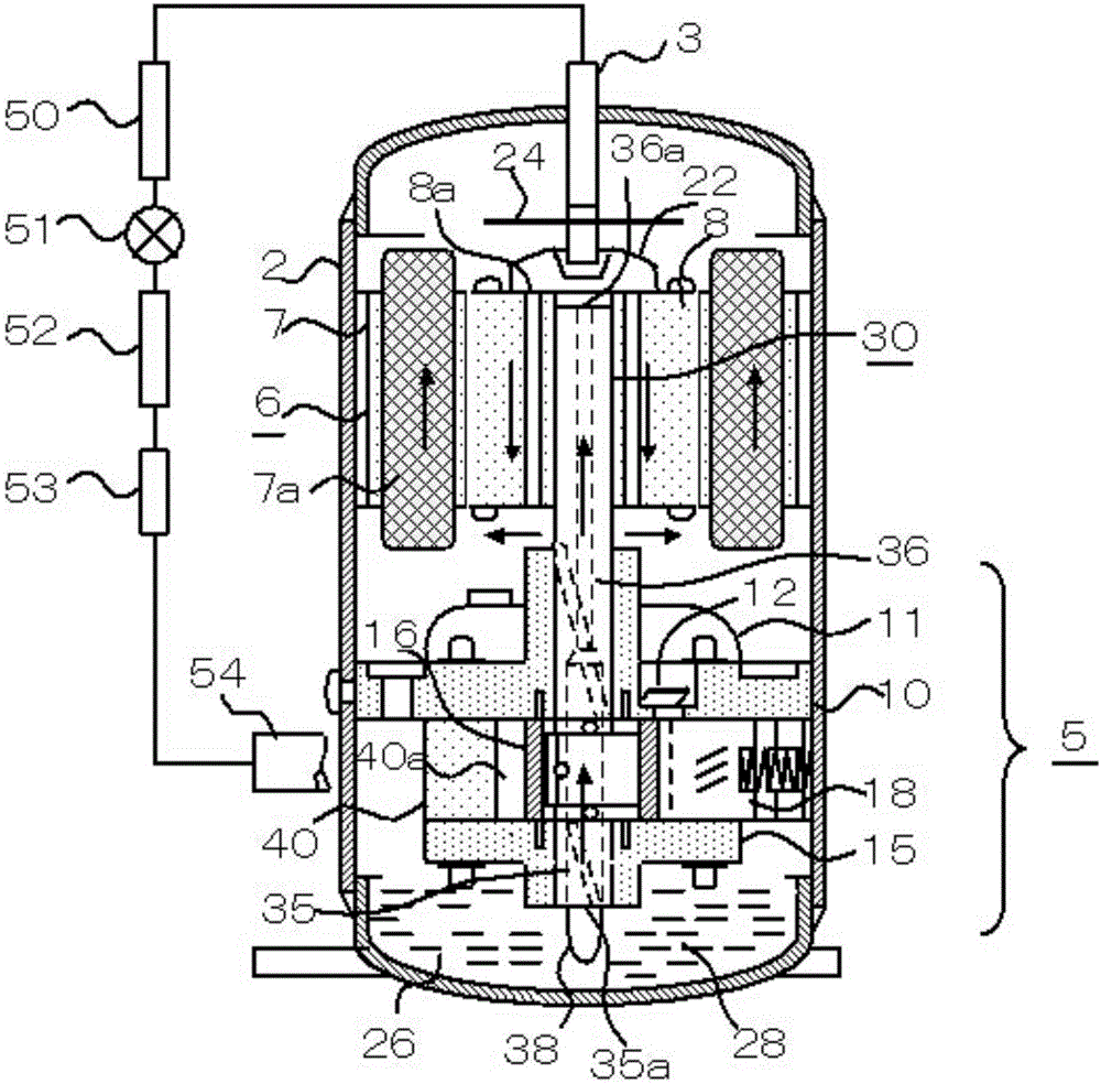
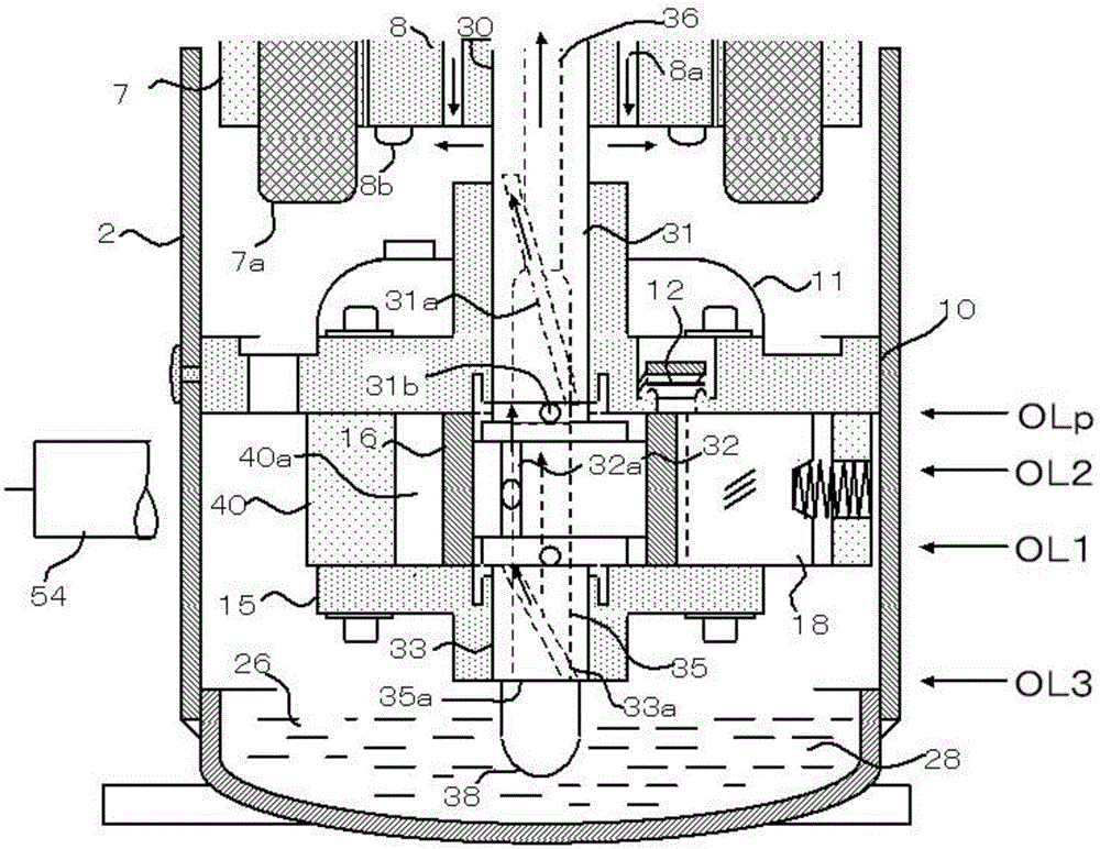
[0046] figure 1 with figure 2 Among them, an electric motor 6 (hereinafter referred to as motor 6 ) and a compression mechanism part 5 driven by the motor 6 are fixed on the inner peripheral wall of the sealed casing 2 (hereinafter referred to as casing 2 ) of the rotary compressor.

[0047] Lubricating oil 26 (hereinafter referred to as oil 26 or oil) is stored in an oil storage tank 28 disposed at the bottom of the housing 2 .

[0048] The compression mechanism part 5 includes: a main bearing 10 fixed to the inner peripheral wall of the housing 2, a cylinder 40, an auxiliary bearing 15, a crankshaft 30 slidingly engaged with the above two bearings, a piston 16 driven by the crankshaft 30 to rotate eccentrically, and a reciprocating cylinder. slide 18. An exhaust muffler 11 housing a valve device 12 is disposed on the main bearing 10 .

[0049] The crankshaft 30 is fixed by the rotor 8, and the crankshaft 30 includes: a main shaft 31 slidingly fitted with the main bearing...

Embodiment 2

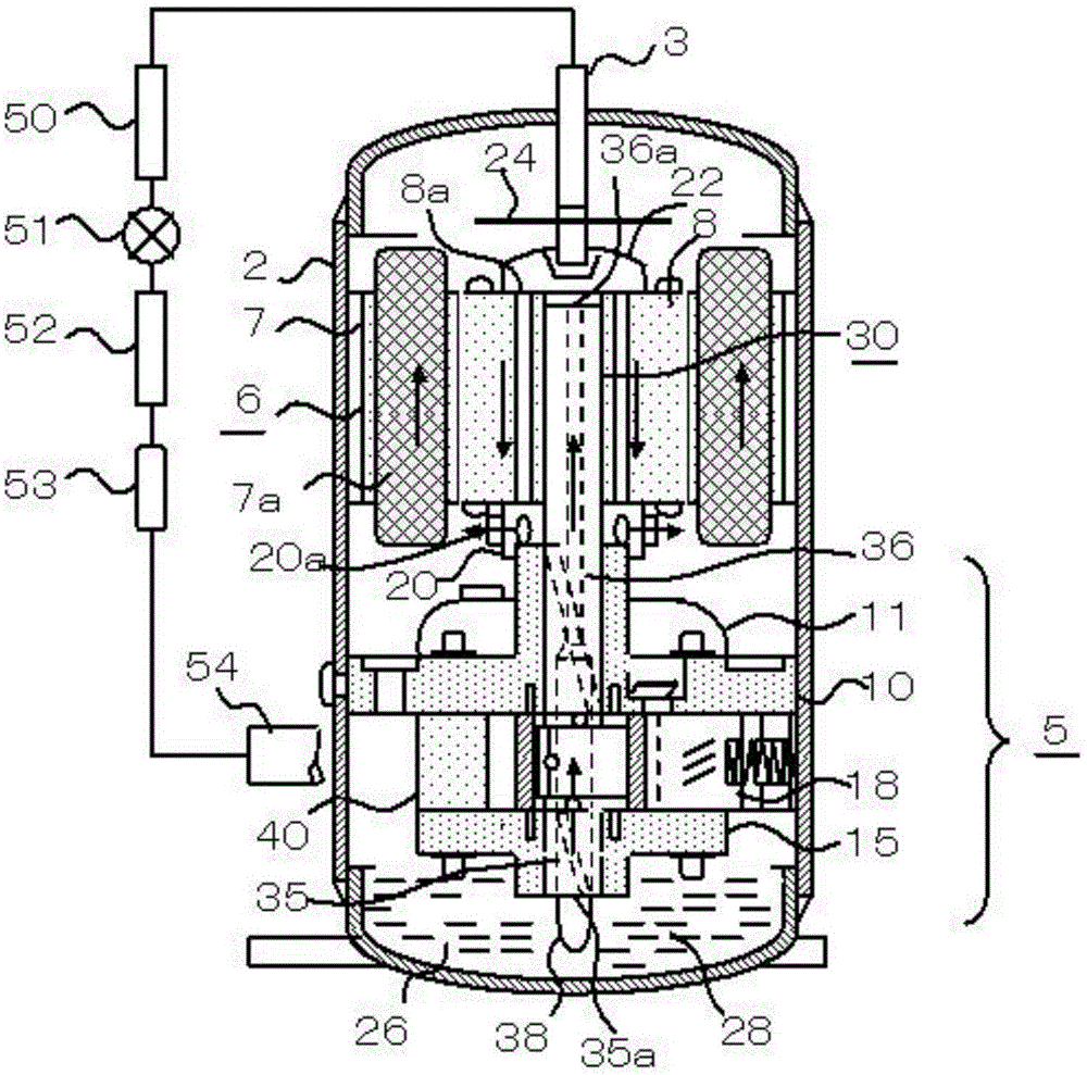
[0069] image 3 with Figure 4 In the shown embodiment 2, compared with the embodiment 1, in order to increase the pressure drop of the pump chamber, a rotating chamber 20 is added at the outlet of the rotor air hole 8a. On the outer peripheral wall of the rotary chamber 20, a plurality of cylindrical rotary windows 20a are arranged.

[0070] The rotation chamber 20 fixed to the lower end of the rotor 8 by the rotor rivet 8 b is located on the outer periphery of the main bearing 10 near the bearing upper end. This rotation gap (C) is designed to be 0.2mm or less in order to prevent gas leakage. In Embodiment 2, the rotation diameter of the rotation window 20 is larger than the rotation diameter of the rotor air hole 8a. By processing the diameter and shape of the rotation window 20, the pressure drop of the pump chamber 35 can be increased compared with the embodiment 1.

[0071] Under the condition that the oil level of the oil storage tank 28 is stable from the lower end ...


PUM


Abstract

The invention discloses a rotary compressor and a refrigeration device with the same. An electric motor composed of a stator and a rotor, a compression mechanism part driven by the rotor, and an oil storage groove are received in a sealed shell equipped with an exhaust pipe, of the rotary compressor, and the rotor is provided with a rotor air vent penetrating through the rotor; the compression mechanism part comprises a crankshaft, the crankshaft is provided with a shaft core channel penetrating through the crankshaft, and the shaft core channel is provided with a shaft end inlet and a shaft end outlet opened in the two ends of the crankshaft; and the rotary compressor further comprises a rotor cover fixed on the rotor, the shaft end outlet and the inlet of the rotor air vent are located in the rotor cover, and lubricant oil flows according to a direction of a shaft end inlet, a shaft core channel and a shaft end outlet opened in the oil storage groove, the rotor cover, and the outlet of the rotor air vent. The rotary compressor disclosed by the embodiment of the invention is capable of preventing rapid oil discharge under a high-flow running condition, increasing the oil pumping amount and pump lift of the shaft core channel, preventing the rotor from overheating and increasing the oil discharge amount.

Description

technical field [0001] The invention relates to the refrigeration field, in particular to a rotary compressor and a refrigeration device having the same. Background technique [0002] In the more than 70 years of rotary compressor history, the method of oil supply to the crankshaft has basically remained unchanged. Through the centrifugal force generated by the rotation of the crankshaft shaft core hole, the oil sucked up from the oil storage tank is supplied to the crankshaft, the bearings and pistons that slide with it and other sliding parts. In addition, the amount of pump oil produced by the centrifugal oil supply method is proportional to the inner diameter of the pump chamber of the crankshaft, the rotation speed, and the oil level of the oil storage tank. [0003] Therefore, when the crankshaft rotates at a low speed of 20rps or less, when starting, defrosting operation, or high-speed operation (these are called high-flow operating conditions), the oil volume and oi...

Claims


Application Information

Patent Timeline
Patent Type & Authority Applications(China)
IPC IPC(8): F04C29/02F04C29/12
CPCF04C29/02F04C29/12
Inventor 小津政雄李盖敏王玲
Owner GUANGDONG MEIZHI COMPRESSOR
Learn More