Variable displacement variable pressure adjustment load matching electro-hydraulic position tracking control method

A technology of pressure regulation and load matching, which is applied in the direction of fluid pressure actuators, servo motor components, mechanical equipment, etc. It can solve the problems of poor position control characteristics, energy loss, and low energy utilization rate, so as to reduce pressure loss. , Improve the effect of tracking accuracy

Active Publication Date: 2017-05-10
TONGJI UNIV
View PDF3 Cites 8 Cited by
  • Summary
  • Abstract
  • Description
  • Claims
  • Application Information

AI Technical Summary

Problems solved by technology

The traditional electro-hydraulic position servo system uses a quantitative pump + relief valve oil supply unit or a constant pressure variable pump oil supply unit to provide a constant pressure to the load, but the pressure required by the load changes, and the oil supply pressure is not equal to the load pressure. A pressure drop occurs on the load servo valve, resulting in energy loss, and the energy utilization rate of the entire system is low
On the other hand, if only reducing the oil supply pressure to save energy, the response speed of the traditional position feedback control will be slowed down, and the position control characteristics will be deteriorated.

Method used


Image

  • Variable displacement variable pressure adjustment load matching electro-hydraulic position tracking control method
  • Variable displacement variable pressure adjustment load matching electro-hydraulic position tracking control method
  • Variable displacement variable pressure adjustment load matching electro-hydraulic position tracking control method

Examples


Embodiment Construction

[0061] The present invention will be described in detail below in conjunction with the accompanying drawings and specific embodiments. This embodiment is carried out on the premise of the technical solution of the present invention, and detailed implementation and specific operation process are given, but the protection scope of the present invention is not limited to the following embodiments.

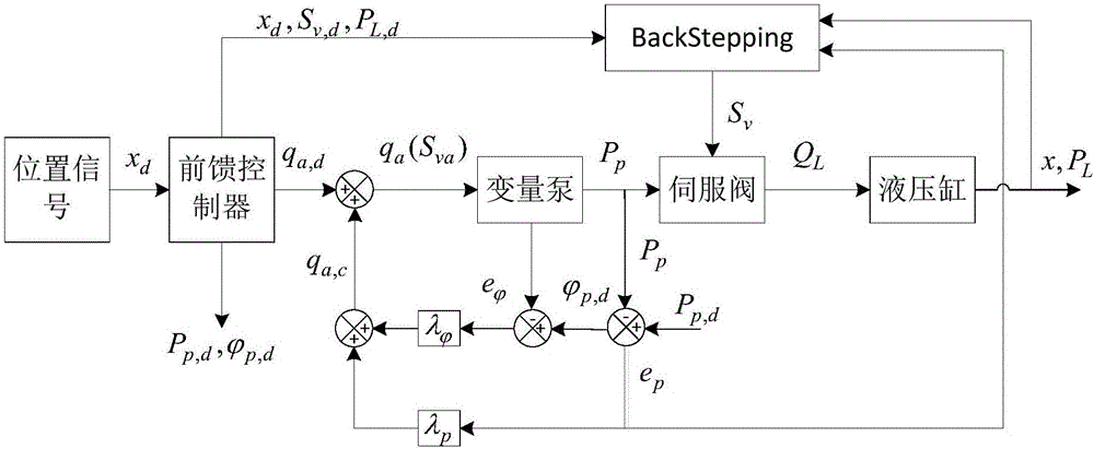
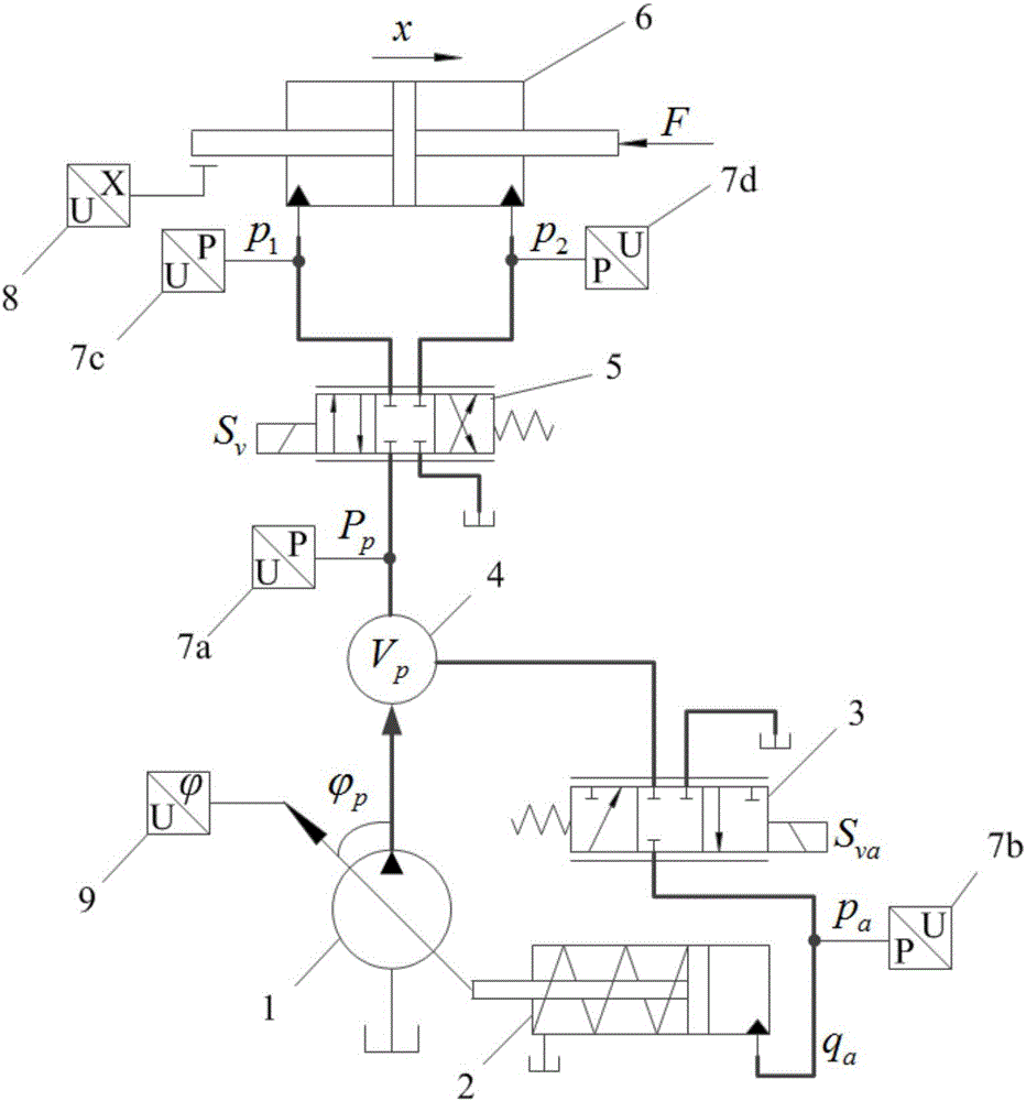
[0062] Such as figure 2 The electro-hydraulic position control system shown includes variable pump 1, variable cylinder 2, variable control valve 3, pump outlet pipe cavity 4, servo valve 5, hydraulic cylinder 6, pressure sensors 7a, 7b, 7c, 7d, hydraulic cylinder Displacement sensor 8, and variable pump swash plate inclination sensor 9. Pressure sensors 7a, 7b, 7c, 7d are used to measure the pump outlet pressure P p , variable cylinder pressure p a , the pressure p of the left and right chambers of the hydraulic cylinder 1 ,p 2 , where the load pressure P L =p 1 -p 2 ;The hy...


PUM


Abstract

The invention relates to a variable displacement variable pressure adjustment load matching electro-hydraulic position tracking control method. The variable displacement variable pressure adjustment load matching electro-hydraulic position tracking control method comprises the following steps that (1) a hydraulic cylinder speed signal v<d> is obtained, and the servo valve open degree feedforward control quantity S<v,d> is calculated; (2) the pump outlet pressure feedforward control quantity P<p,d> and the pump variable control valve feedforward control quantity q<a,d> are subjected to back calculation through the inverse model method; and (3) the pump swash plate inclination angle phi, the pump outlet pressure P, the hydraulic cylinder displacement x and the hydraulic cylinder load pressure P<L> are obtained, the variable control valve actual control quantity q is obtained through the linear feedback method, the servo valve actual control quantity S<v> is obtained through the Backstepping method, and hydraulic cylinder position tracking control is achieved. According to the variable displacement variable pressure adjustment load matching electro-hydraulic position tracking control method, compared with the existing constant pressure adjustment electro-hydraulic position control technology, the pump outlet pressure changes according to the pressure required by loads; pressure loss is reduced; the system efficiency is improved; and meanwhile, the method that feedforward control and feedback control are combined is adopted, so that the hydraulic cylinder position tracking precision is high.

Description

technical field [0001] The invention relates to an electro-hydraulic position tracking control method, in particular to an electro-hydraulic position tracking control method for adjusting load matching with variable displacement and variable pressure. Background technique [0002] The electro-hydraulic position servo system is widely used in aircraft rudder surface control, machine tool feed system, mechanical arm movement mechanism, wind turbine blade pitch angle control and other fields. The traditional electro-hydraulic position servo system uses a quantitative pump + relief valve oil supply unit or a constant pressure variable pump oil supply unit to provide a constant pressure to the load, but the pressure required by the load changes, and the oil supply pressure is not equal to the load pressure. A pressure drop occurs on the load servo valve, resulting in energy loss, and the energy utilization rate of the entire system is low. On the other hand, if only reducing the...

Claims


Application Information

Patent Timeline
Patent Type & Authority Applications(China)
IPC IPC(8): F15B13/02F15B13/16
CPCF15B13/02F15B13/16
Inventor 李晶廖攀辛东华
Owner TONGJI UNIV
Why Eureka
Try Eureka