
valve well valve

A technology of valve wells and valves, applied in valve details, valve devices, sliding valves, etc., can solve the problems of inflexible valve opening and closing, difficult operation, poor safety guarantee, etc., and achieve easy and fast opening or closing, and good operation safety , the effect of meeting the application requirements

Active Publication Date: 2018-11-02
JIANGMEN XINHUI DISTRICT LONGQUAN SEWAGE TREATMENT CO LTD
View PDF13 Cites 0 Cited by
  • Summary
  • Abstract
  • Description
  • Claims
  • Application Information

AI Technical Summary

Problems solved by technology

[0005] 1. The installation position of the valve in the valve well is low, the space in the well is small, it is not easy to stand, and it is not easy to exert force, resulting in time-consuming and laborious operation
[0006] 2. Sewage and sludge have accumulated in the valve well for a long time, which has a strong odor and is difficult to operate
[0007] 3. The moisture in the valve well and the erosion of acid, alkali and salt will easily lead to corrosion and corrosion of the parts of the valve, resulting in inflexible opening and closing of the valve, which cannot be opened and closed by conventional methods, and requires additional relay tools to do it reluctantly, which is time-consuming and labor-intensive
[0011] The above two major reasons lead to the traditional valve well closed and opened with high labor intensity, low work efficiency and poor safety guarantee, which directly affect the progress of production and lead to a decrease in operating efficiency

Method used


Image

  • valve well valve
  • valve well valve
  • valve well valve

Examples


Embodiment Construction

[0047] The technical solutions in the embodiments of the present invention will be clearly and completely described below in conjunction with the accompanying drawings in the embodiments of the present invention. Obviously, the described embodiments are only some, not all, embodiments of the present invention. Based on the embodiments of the present invention, all other embodiments obtained by persons of ordinary skill in the art without making creative efforts belong to the protection scope of the present invention.

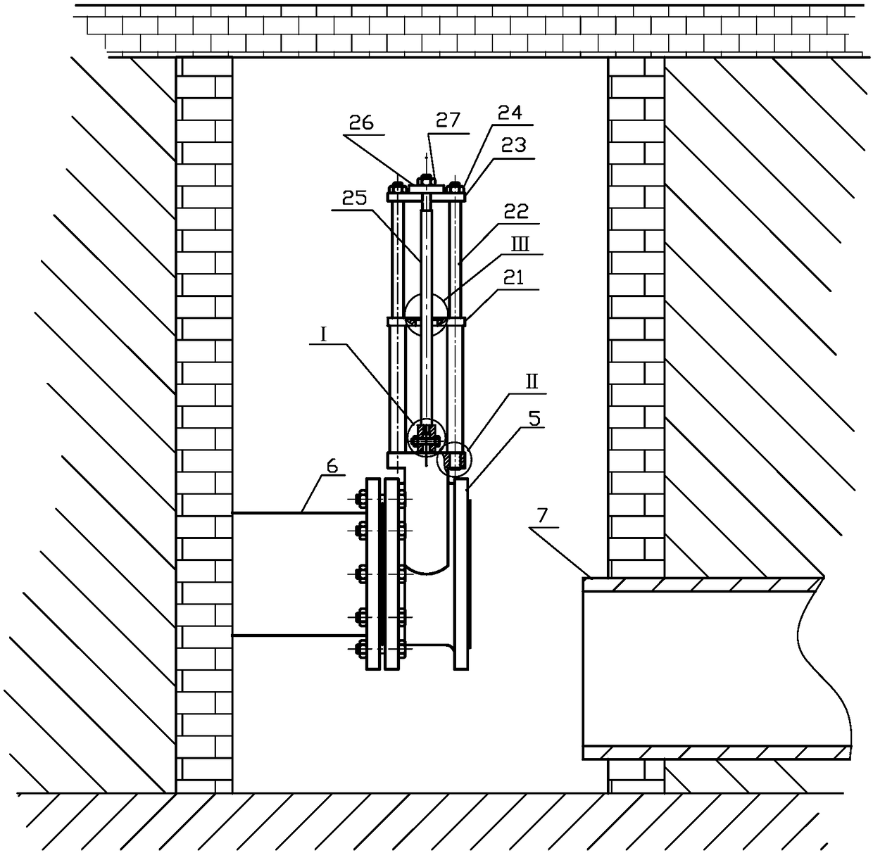
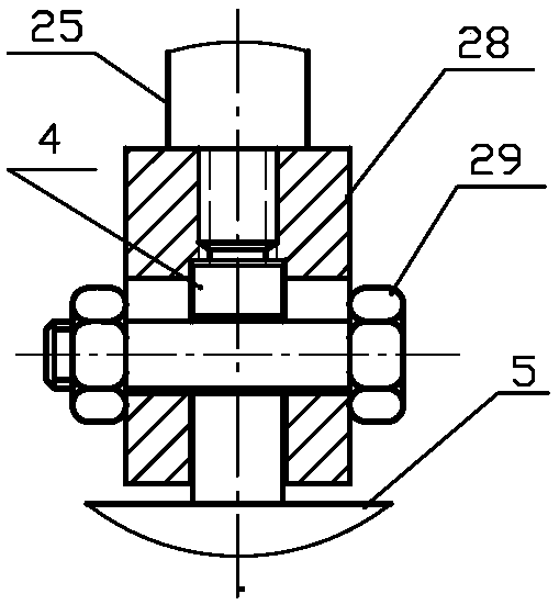
[0048] Such as Figures 2a-9bAs shown, the novel valve well valve includes gate plate 4, valve body 5, lower support 21, pole 22, upper support 23, pull rod 25, top arm 26, pull arm 28. The valve body 5 is fixedly installed on the nozzle of the vent pipe 6 terminal through a flange, and the well arm opposite to the vent pipe 6 is provided with a vent pipe 7, such as figure 1 shown. Described strut 22 is respectively installed on the threaded hole of valve body...


PUM


Abstract

The invention discloses a novel valve well valve which comprises a gate plate, a valve body, a lower supporting base, supporting rods, an upper supporting base, pull rods, a top arm and a pull arm, wherein the valve body is fixedly mounted on a tube opening of a blow-down tube in a valve well, and an emptying tube is arranged on the well wall opposite to the blow-down tube; the supporting rods are separately mounted on side corner positions of the top surface of the valve body; the upper ends of the supporting rods are connected with the upper supporting base in a penetrating mode, and the middle parts of the supporting rods are connected with the lower supporting base in the penetrating mode; the pull rods are mounted at the two ends of the pull arm; the pull arm is in blocking connection with the gate plate through a blocking slot, and is connected with the gate plate through a penetrating pin; and the top arm is arranged above the upper supporting base, and is connected to the upper ends of the pull rods in the penetrating mode. The valve is simple in structure, is low in manufacturing cost, is long in service life, is simple to mount, is convenient to maintain, is free of repair, is low in opening or closing labor intensity, is high in working efficiency, and is free of hidden danger in aspect of safety, completely can overcome the defects caused by a conventional valve well valve, meets application needs, and changes the condition that an existing technology is laggard.

Description

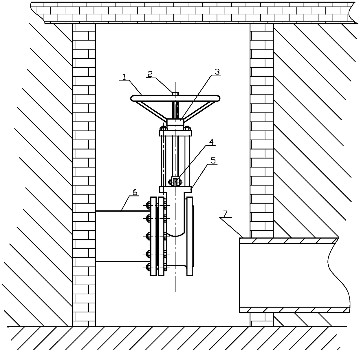
technical field [0001] The invention belongs to the equipment field of sewage treatment industry, and in particular relates to a novel valve well valve for sewage treatment. Background technique [0002] In sewage treatment projects, according to the needs of the production process, some valves need to be installed in "well pits". Such "well pits" are called valve wells. The depth of the valve well is generally about 2 meters, and the width ranges from 1 to 2 meters, such as the vent valve of the oxidation ditch, the vent valve of the hydrolysis tank, etc. When the traditional valve well valve is opened or closed, the operator needs to go down into the well and rotate it by hand. figure 1 The valve hand wheel 1 is shown, and then the hand wheel 1 drives the valve stem 2, and the valve stem 2 pulls or compresses the gate 4 through the rotation of the valve stem nut and the bearing assembly 3, so that the gate 4 moves little by little. A long rise or fall forces the valve to...

Claims


Application Information

Patent Timeline
Patent Type & Authority Patents(China)
IPC IPC(8): F16K3/02F16K31/12
CPCF16K3/0254F16K3/0281F16K31/12
Inventor 陈光兴游卫强陈浩苏爱萍
Owner JIANGMEN XINHUI DISTRICT LONGQUAN SEWAGE TREATMENT CO LTD
Learn More