Steel tube clamping device

A technology of clamps and steel pipes, which is applied in the direction of pipe supports, pipes/pipe joints/pipe fittings, mechanical equipment, etc., can solve the problems of positioning and clamping accuracy that cannot be guaranteed, and achieve the effect of improving clamping accuracy

Inactive Publication Date: 2017-05-10
黄斌
View PDF6 Cites 7 Cited by
  • Summary
  • Abstract
  • Description
  • Claims
  • Application Information

AI Technical Summary

Problems solved by technology

[0003] Steel pipes are not only used to transport fluids and powdery solids, exchange heat, and manufacture mechanical parts and containers. It is also a kind of economical steel. Using steel pipes to manufacture building structure grids, pillars and mechanical supports can reduce weight and save metal by 20-40%. , and can realize factory-like mechanized construction. The use of steel pipes to manufacture road bridges can not only save steel and simplify construction

Method used


Image

  • Steel tube clamping device

Examples


Embodiment Construction

[0012] In order to make the object, technical solution and advantages of the present invention clearer, the present invention will be further described in detail below in conjunction with the accompanying drawings and embodiments. It should be understood that the specific embodiments described here are only used to explain the present invention, not to limit the present invention.

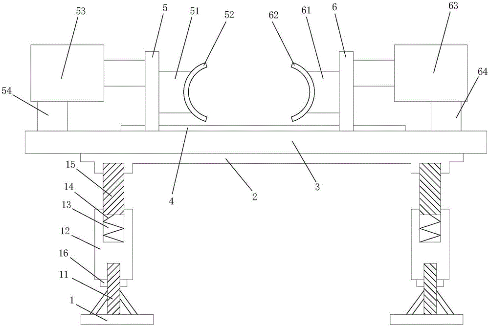
[0013] Such as figure 1 As shown, the steel pipe clamp includes a support base 1, on which a screw 11 is installed, and the screw 11 is installed in a threaded hole at the lower end of the sleeve rod 12, and on the sleeve rod 12 The upper end of 12 is provided with a blind hole 13, a spring 14 is installed in the blind hole 13, and a push rod 15 is installed in the blind hole 13, and the upper end of the push rod 15 is installed in the groove of the top plate 2 A support plate 3 is installed above the top plate 2, a slide rail 4 is installed above the support plate 3, and a slide column A5 and a s...


PUM


Abstract

The invention discloses a steel tube clamping device. The steel tube clamping device comprises a supporting base, a screw rod is arranged on the supporting base, the screw rod is arranged in a threaded hole which is located at the lower end of a sleeve rod, a blind hole is formed in the upper end of the sleeve rod, a spring is arranged in the blind hole, a mandril is arranged in the blind hole, and the upper end of mandril is arranged in a groove of a top plate; a supporting plate is arranged above the top plate, a slide rail is arranged above the supporting plate, a sliding column A and a sliding column B are slidably arranged on the slide rail, one side of the sliding column A is provided with a fixed column A, one side of the fixed column A is provided with a clamping device A, one side of the sliding column B is provided with a fixed column B, one side of the fixed column B is provided with a clamping device B, the other side of the sliding column A is provided with an actuator A, the actuator A is arranged on a support body A, the support body A is arranged above the supporting plate, the other side of the sliding column B is provided with an actuator B, an actuator B is arranged on a support body B, and the support body B is arranged above the supporting plate.

Description

technical field [0001] The invention relates to the technical field of machinery, in particular to a steel pipe clamp. Background technique [0002] The development of steel pipe production technology began with the rise of the bicycle manufacturing industry, the development of petroleum in the early 19th century, the manufacture of ships, boilers, and aircraft during the two world wars, the manufacture of thermal power boilers after the Second World War, the development of the chemical industry and Drilling, production and transportation of oil and natural gas have strongly promoted the development of steel pipe industry in terms of variety, output and quality. The steel pipe is used to transfer fluid and powder, exchange heat and produce mechanical parts and containers, what's more it's a kind of economical steel. Using steel pipes to manufacture building structure grids, pillars and mechanical supports can reduce weight, save metal by 20-40%, and realize factory-like mec...

Claims


Application Information

Patent Timeline
IPC IPC(8): F16L3/10F16L3/205
CPCF16L3/10F16L3/2056
Inventor 黄斌
Owner 黄斌
Why Eureka
Try Eureka