
A Method of Gyro Zero Offset Correction after Shelling

A technology of gyroscope bias and gyroscope, which is applied to measurement devices, instruments, and navigation through velocity/acceleration measurement, etc., can solve problems such as attitude measurement result errors, and achieve the effect of solving huge errors and improving attitude measurement accuracy.

Active Publication Date: 2019-01-04
ZHONGBEI UNIV
View PDF4 Cites 0 Cited by
  • Summary
  • Abstract
  • Description
  • Claims
  • Application Information

AI Technical Summary

Problems solved by technology

[0003] In order to solve the problem that the zero-bias of the missile-borne MEMS gyroscope causes huge errors in the attitude measurement results of the projectile, the present invention provides a method for correcting the zero-bias of the gyroscope after shelling

Method used


Image

  • A Method of Gyro Zero Offset Correction after Shelling
  • A Method of Gyro Zero Offset Correction after Shelling
  • A Method of Gyro Zero Offset Correction after Shelling

Examples


Embodiment Construction

[0024] A method for correcting the zero bias of a gyroscope after shelling is realized by the following steps:

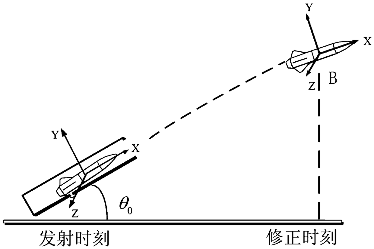
[0025] Step S1: Define the launch coordinate system of the projectile as the navigation coordinate system, referred to as the n system; define the projectile coordinate system as the carrier coordinate system, referred to as the b system; the inertial coordinate system is referred to as the i system; is the zero point correction time; define the flight time of the projectile from the launching point to the 20m of the gun mouth as t;

[0026] Step S2: Before launching the projectile, perform initial alignment on the missile-borne inertial navigation system;

[0027] Step S3: After the projectile is launched, according to the real-time output of the MEMS gyroscope in the missile-borne inertial navigation system, extract the yaw angle ψ of the projectile at the time of zero correction 1 , pitch angle θ 1 , roll angle γ 1 ;

[0028] Step S4: Use a high-precision thr...


PUM


Abstract

The invention relates to a missile-borne MEMS (Micro-electromechanical System) gyro, and in particular to a post-bombardment gyro bias correction method. The invention solves the problem that the bias of a missile-borne MEMS gyro can lead to a great error in a missile body attitude measurement result. The post-bombardment gyro bias correction method is implemented by adopting the following steps: (Step S1) defining the moment of a missile body being 20m away from a muzzle as a zero correction moment; (step S2) initially aiming a missile-borne inertial navigation system; (Step S3) extracting a yaw angle Psi 1, pitch angle Theta 1 and rolling angle Gamma 1 of the missile body at the zero correction moment according to a real-time output of an MEMS gyro in the missile-borne inertial navigation system; (Step S4) working out a pitch angle Theta 2 and rolling angle Gamma 2 of the missile body at the zero correction moment according to (img file='DDA0001184784270000011.TIF' wi'475' he='71' / ); (Step S5) working out a zero variation of the MEMS gyro before and after the launch of the missile body according to Psi 1, Theta 1, Gamma 1, Theta 2 and Gamma 2; (Step S6) working out an accurate real-time output of the MEMS gyro. The invention is applicable to missile body attitude measurement.

Description

technical field [0001] The invention relates to a bomb-borne MEMS gyroscope, in particular to a method for correcting the zero bias of the gyroscope after shelling. Background technique [0002] With the development of MEMS technology, MEMS gyroscopes are widely used in weaponry systems due to their incomparable advantages such as small size, light weight, low power consumption, and high reliability. The MEMS gyroscope in the missile-borne inertial navigation system (referred to as the missile-borne MEMS gyroscope) is the core component of the system, and its accuracy and performance play a vital role in the attitude measurement of the missile body. In practical applications, when the projectile is launched, the missile-borne MEMS gyroscope will be subjected to a large overload, which will cause the zero-bias of the missile-borne MEMS gyroscope (that is, the zero position of the missile-borne MEMS gyroscope will be significantly shifted) , resulting in huge errors in the at...

Claims


Application Information

Patent Timeline
Patent Type & Authority Patents(China)
IPC IPC(8): G01C25/00G01C21/18
CPCG01C21/18G01C25/005
Inventor 刘俊李杰张晓明张樨申冲冯凯强王一焕郑涛
Owner ZHONGBEI UNIV
Learn More