Calibrating device for fuel oil re-fuelling device and use method thereof

A technology for verification devices and fuel dispensers, applied in measuring devices, testing/calibration devices, instruments, etc., can solve the problems of large fuel dispenser error influence, fuel dispenser error influence, slow temperature response speed, etc., and achieve actual measurement accuracy High, less error factors, simple production process

Pending Publication Date: 2017-05-10
李盛
View PDF7 Cites 2 Cited by
  • Summary
  • Abstract
  • Description
  • Claims
  • Application Information

AI Technical Summary

Problems solved by technology

[0004] At present, there are two types of temperature measuring equipment: one is to use a digital display thermometer, the minimum graduation value of the thermometer is 0.1°C, and the measuring range is -30~60°C. Short, when in use, it cannot reach the central part of the standard measuring instrument, and can only measure the temperature on the upper surface
The other is to use a glass thermometer. When using this thermometer for measurement, the glass thermometer needs to be exposed to the liquid surface by 1.5cm, otherwise it needs to be corrected, and the center position of the standard measuring device cannot be reached during the measurement process, and the temperature response speed is slow. When the thermometer measurement is completed and the liquid level reading is taken, due to factors such as temperature changes, the uncertainty of temperature measurement in the actual process will result.
[0005] (2) Quantitative refueling and non-quantitative refueling have an impact on the error of the fuel dispenser
Due to the existence of the electromagnetic valve in the fuel dispenser, the metering error of the fuel dispenser is received by the amount of closing the valve in advance and the actual refueling V 1 The impact of the general setting of the valve closing in advance V 1 is a constant, so when there is little refueling, it has a greater impact on the error of the fuel dispenser. In actual operation, the test results of quantitative refueling and non-quantitative refueling are different, and the current regulations only stipulate the error of quantitative refueling. The error of non-quantitative refueling in real life is not considered
Since the standard metal utensils do not have a suitable inspection device during the verification period, if the tank body is deformed during use, it is difficult to find out in time, and the problem can only be found after the next verification cycle is sent to the superior metrology department for verification. The measurement accuracy cannot be guaranteed. Due to the concave shape of the liquid level display, the standard metal utensils still have human visual errors in the liquid level degree device during use.
The verification process requires two sets of small flow tanks and large flow tanks to cooperate with the verification, the equipment is complicated and it is easy to cause errors

Method used


Image

  • Calibrating device for fuel oil re-fuelling device and use method thereof
  • Calibrating device for fuel oil re-fuelling device and use method thereof
  • Calibrating device for fuel oil re-fuelling device and use method thereof

Examples


Embodiment Construction

[0034] In order to illustrate the present invention in detail, the present invention will be further described in detail below in conjunction with specific implementation examples, but the described examples should not be interpreted in a limiting manner.

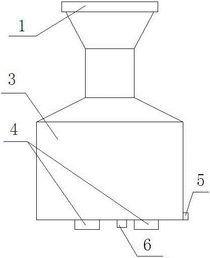
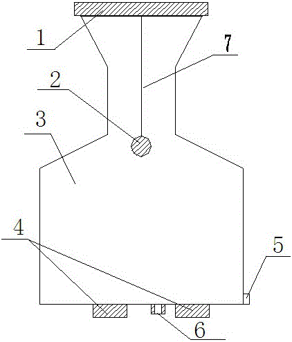
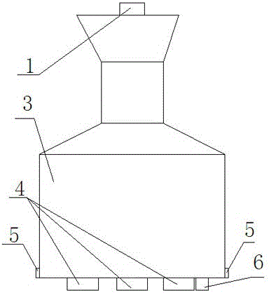
[0035] From Figure 1-Figure 4 It can be seen that the present invention contains a tank body 3, a tensile load sensor 1, a solid standard metal ball 2 of known volume, a gravity load sensor 4, a horizontal bubble 5, a drain hole 6, a gravity load sensor 4 and a drain hole 6 It is arranged at the bottom of the tank body 3, the horizontal bubble 5 is arranged on the lower side wall of the tank body 3, the tensile load sensor 1 is installed on the upper cover of the tank body 3, and the solid standard metal ball 2 is located in the inner cavity of the tank body 3, and passes through Thin nylon wire 7 is suspended on the tensile load sensor 1 .

[0036] There are three gravity load sensors 4, which are evenly distributed on t...


PUM


Abstract

The invention discloses a calibrating device for a fuel oil re-fuelling device and a use method thereof. The calibrating device comprises a tank body (3), a tensile force load sensor (1), a known volume solid standard metal ball (2), a gravity load sensor (4), a level bubble (5) and a liquid draining hole (6), wherein the gravity load sensor and the liquid draining hole are arranged at the bottom of the tank body; the level bubble is formed on the side wall of the tank body; the tensile force load sensor is arranged on an upper cover of the tank body; the solid standard metal ball is located in an inner chamber of the tank body and is suspended on the tensile force load sensor. In a use process, to-be-measured liquid is injected into the tank body, the weight of the to-be-measured liquid is measured by the gravity load sensor, the tensile force is measured through the tensile force load sensor so that the density of the to-be-measured liquid can be calculated, the volume of the to-be-measured liquid is calculated according to a formula, and then a calculated result is compared with a numerical value of the re-fuelling device, so that a measuring result can be acquired. The calibrating device disclosed by the invention has the advantages of simple structure, convenience in use, accurate calibration, small error and high accuracy.

Description

technical field [0001] The invention relates to a verification device for a fuel oil dispenser, in particular to a verification device for a fuel dispenser with a weighing method. Background technique [0002] The fuel tanker used for oil trade settlement is a measuring instrument for compulsory verification. How to ensure the accuracy of the tanker is a major issue related to people's livelihood. However, the current tanker verification technology is not perfect, and various factors have a great impact on the verification results. . According to the requirements of JJG443-2015 "Verification Regulations for Fuel Dispensers" (referred to as regulations), the current method used is the standard measuring device comparison method, that is, a certain volume of oil is pumped out from the fuel dispenser and measured using a standard metal container. The tanker displays numerical comparisons to calculate the error, but in the actual process, various influencing factors are too lar...

Claims


Application Information

Patent Timeline
Patent Type & Authority Applications(China)
IPC IPC(8): G01F25/00
CPCG01F25/0084
Inventor 李盛
Owner 李盛
Why Eureka
Try Eureka