
Rotating equipment vibration monitoring protection device channel abnormity detection method

A vibration monitoring and protection device technology, which is applied to measuring devices, measuring ultrasonic/sonic/infrasonic waves, instruments, etc., can solve problems such as simple functions, abnormal vibration signal channels, time-consuming and labor-intensive problems, and achieve improved reliability and perfect self-inspection Effect

Active Publication Date: 2017-05-10
江苏沙河抽水蓄能发电有限公司 +2
View PDF6 Cites 4 Cited by
  • Summary
  • Abstract
  • Description
  • Claims
  • Application Information

AI Technical Summary

Problems solved by technology

At present, there are many products at home and abroad. Some products have simple functions and often misjudgment; Redundant configuration and mutual verification of sensor signals at the same measuring point are realized, and the cost is relatively high
Once the channel is abnormal (the sensor is abnormal or the sampling channel of the monitoring protection device is abnormal), the device cannot distinguish it from the real fault signal, and it needs to stop for detection, which is time-consuming and laborious; if the channel abnormality cannot be identified in time, it will also cause the vibration monitoring and protection device to malfunction. incorrect action

Method used


Image

  • Rotating equipment vibration monitoring protection device channel abnormity detection method
  • Rotating equipment vibration monitoring protection device channel abnormity detection method
  • Rotating equipment vibration monitoring protection device channel abnormity detection method

Examples


Embodiment

[0024] Embodiment: The present invention designs a correlation-based detection method for the channel abnormality of the vibration monitoring protection device of the rotating equipment. The specific implementation of this method will be described below in combination with the specific situation of a 300MW hydroelectric unit in a certain power plant, and the channel abnormality detection of the above X-direction measuring point as an example.

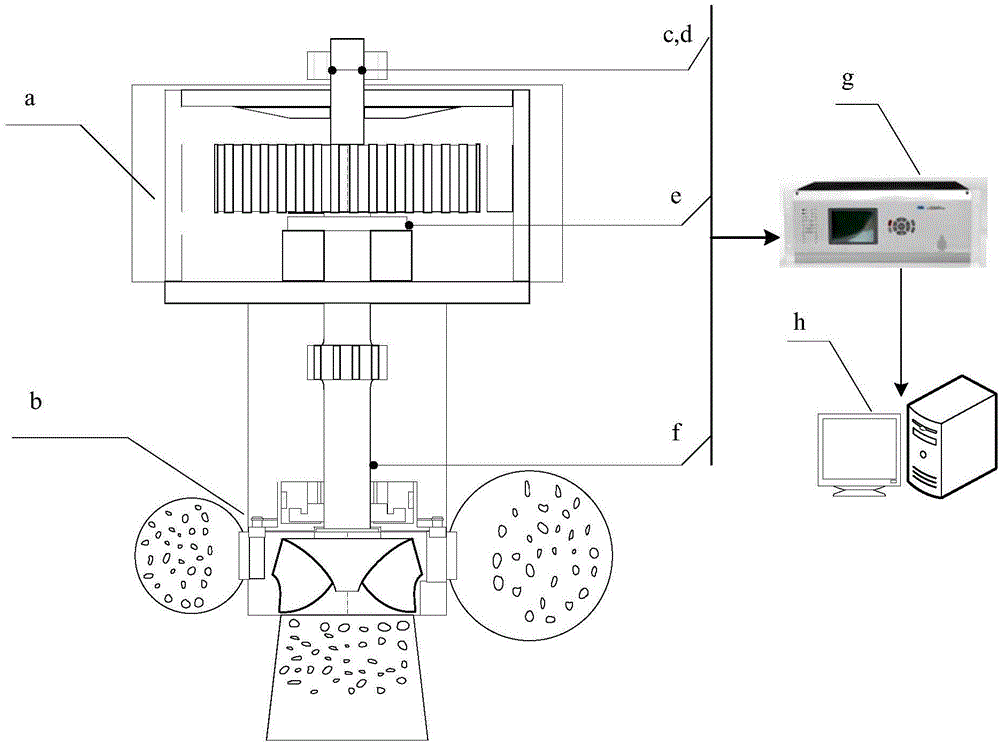
[0025] The main wiring diagram and the wiring of the rotating equipment vibration monitoring protection device and the background analysis system are attached figure 1 shown.

[0026] The design water head of the turbine is 51m, and the design flow is 114m 3 / s, rated output 306MW, runner installation elevation 205m, rated speed 500rpm, number of runner blades 7;

[0027] The rated capacity of the generator is 300MW, the rated power factor is 0.9, and the rated voltage is 20kV.

[0028] Set a set of swing signal measuring points in t...


PUM


Abstract

The invention discloses a rotating equipment vibration monitoring protection device channel abnormity detection method. The rotating equipment vibration monitoring protection device channel abnormity detection method comprises steps that a vibration monitoring protection device is used to acquire correlation coefficients of various channels according to positions of detection points corresponding to the various channels and the characteristics of the rotating equipment, and weights are set according to engineering experience; the vibration monitoring protection device is used for the real-time monitoring of the vibration data of the various channels, and is used to detect whether the changing trend of the vibration data meets the correlation constraints of the channels; the vibration signals of one channel are enhanced or weakened abnormally, and the vibration signals of other related channels are not changed, and the situation is repeated a plurality of times, the channel is determined to be abnormal, and abnormality of sensors and abnormity of device sampling channels are included. By adopting the analysis and the real-time detection of the vibration detection point correlation, whether the abnormal change of the single channel meets the correlation constraints is determined, and therefore the self-inspection of the rotating equipment vibration monitoring protection device is completed, and the reliability of the device is improved.

Description

technical field [0001] The invention relates to the field of state monitoring and diagnosis of rotating equipment, in particular to a channel self-inspection method for vibration signals of a vibration monitoring protection device for rotating equipment. Background technique [0002] Rotating equipment, such as various motors and generators, is widely used in the fields of electric power, metallurgy, mining, transportation, etc., and is the key equipment for enterprise production. With the gradual increase in the requirements for the safe operation of equipment, the condition monitoring of rotating equipment has also attracted more and more attention from users. [0003] The key content of condition monitoring of rotating equipment is vibration monitoring and protection. There are many reasons for mechanical vibration. In addition to product defects, installation defects, and improper operation and maintenance of rotating equipment, abnormal loads (related to the production...

Claims


Application Information

Patent Timeline
IPC IPC(8): G01H17/00G01D18/00
CPCG01D18/00G01H17/00
Inventor 王社生王光杨海学陈佳胜黄锐钟守平吴小放张琦雪陈俊
Owner 江苏沙河抽水蓄能发电有限公司
Learn More