
Shock tunnel diaphragm rupture device

A shock-wave wind tunnel and diaphragm technology, which is used in measurement devices, instruments, aerodynamic tests, etc., can solve the problems of long film rupture time, high cost, complex structure, etc., achieving simple rupture device, saving processing costs, The effect of saving equipment investment

Active Publication Date: 2017-05-10
CHINA ACAD OF AEROSPACE AERODYNAMICS
View PDF5 Cites 14 Cited by
  • Summary
  • Abstract
  • Description
  • Claims
  • Application Information

AI Technical Summary

Problems solved by technology

The high-pressure section and low-pressure section of the shock wave wind tunnel are separated by a diaphragm. Through the sudden rupture of the diaphragm, the driving gas in the high-pressure section drives the test gas in the low-pressure section to form a shock wave to complete the experiment process; The rupture of the membrane is achieved by adding a double-membrane segment. This method of membrane rupture takes a long time and has a complex structure. It is difficult to rupture the membrane under low pressure conditions, and the structure is complex and expensive.

Method used


Image

  • Shock tunnel diaphragm rupture device
  • Shock tunnel diaphragm rupture device
  • Shock tunnel diaphragm rupture device

Examples


Embodiment Construction

[0024] Below in conjunction with accompanying drawing and specific embodiment the present invention is described in further detail:

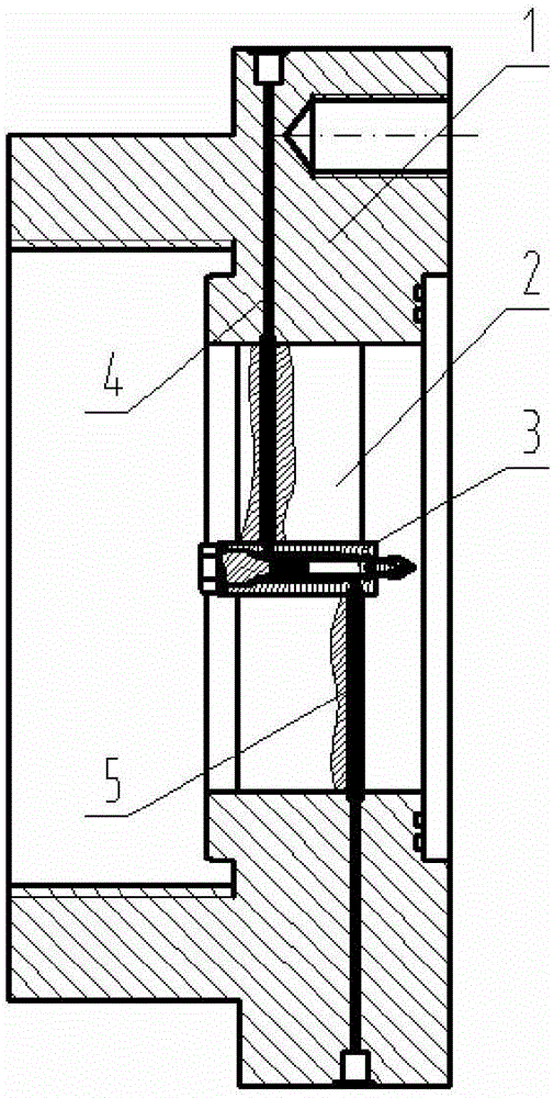
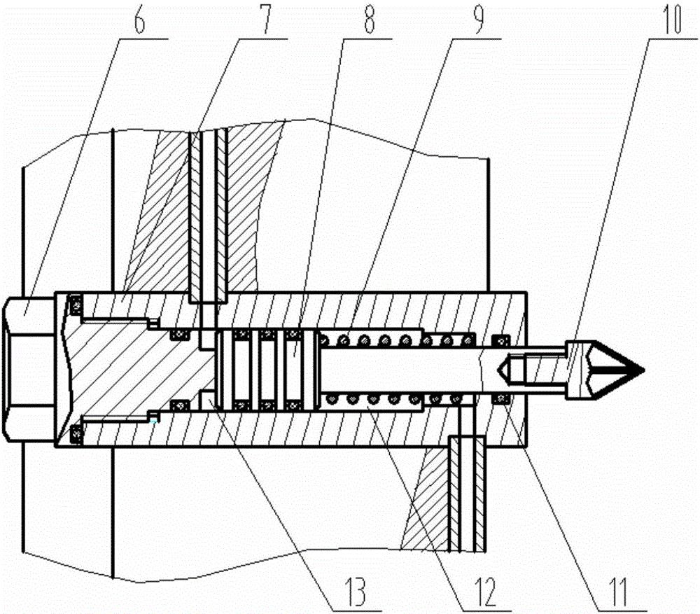
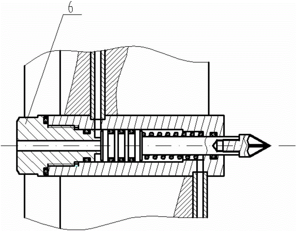
[0025] Such as figure 1 Shown is the structural schematic diagram of the shock tunnel diaphragm rupture device, such as Figure 4 Shown is a schematic diagram of the installation of the shock tunnel diaphragm rupture device in the shock tunnel. It can be seen from the figure that a shock tunnel diaphragm rupture device includes a gun barrel connection structure 1, a vertebral body support plate 2, a ruptured membrane Cone 3, high-pressure chamber pipeline 4, low-pressure chamber pipeline 5, shock tube high-pressure section gun tube 14, shock tube low-pressure section gun tube 15 and diaphragm 16; wherein, the left side of the gun tube connection structure 1 is connected to the shock wave The barrel 14 of the high-pressure section of the tube is fixedly connected, and the right side of the barrel connection structure 1 is fixedly connected with ...


PUM


Abstract

The invention relates to a shock tunnel diaphragm rupture device and belongs to the hypersonic shock tunnel engineering field. The shock tunnel diaphragm rupture device includes a gun barrel connection structure, a cone supporting plate, a diaphragm rupture cone, a high-pressure cavity pipeline, a low-pressure cavity pipeline, a shock tube high-pressure section gun barrel, a shock tube low-pressure section gun barrel and a diaphragm; the left side of the gun barrel connection structure is fixedly connected with the shock tube high-pressure section gun barrel; the right side of the gun barrel connection structure is fixedly connected with the shock tube low-pressure section gun barrel; the cone supporting plate is fixedly installed in the gun barrel connection structure; the diaphragm rupture cone is axially and fixedly installed at the axis of the cone supporting plate through the gun barrel connection structure; the high-pressure cavity pipeline and the low-pressure cavity pipeline are arranged at the outer wall of the diaphragm rupture cone along the radial direction of the gun barrel connection structure; and the diaphragm is fixed between the gun barrel connection structure and the shock tube low-pressure section gun barrel. The diaphragm rupture of a shock tunnel can be both realized under high driving pressure or low driving pressure, diaphragm rupture time is significantly shortened, and the controllability of the diaphragm rupture process is high.

Description

technical field [0001] The invention relates to the field of hypersonic shock tunnel engineering, in particular to a shock tunnel diaphragm rupture device. Background technique [0002] The shock tunnel is a special hypersonic wind tunnel. The shock tunnel is to increase the total temperature of the wind tunnel through the compression of the shock wave. The shock tunnel structure is very simple and the cost is relatively low. With the modern test The development of technology, which can undertake most of the hypersonic aerodynamic and aerothermal measurement tests, plays an increasingly important role in the development of the new model's aerodynamic shape. The high-pressure section and low-pressure section of the shock wave tunnel are separated by a diaphragm. Through the sudden rupture of the diaphragm, the driving gas in the high-pressure section drives the test gas in the low-pressure section to form a shock wave to complete the experiment process; The rupture of the me...

Claims


Application Information

Patent Timeline
IPC IPC(8): G01M9/04
CPCG01M9/04
Inventor 宋可清李辰谌君谋张冰冰韩国祥陈星毕志献蒋博马雁捷韩曙光李海燕刘吴月孙日明王玉东
Owner CHINA ACAD OF AEROSPACE AERODYNAMICS
Learn More