Transformer winding deformation on-line monitoring system by employing fiber grating strain sensors
A technology of strain sensor and transformer winding, applied in the direction of electric winding test, optical device, instrument, etc., can solve the problems of inability to achieve online monitoring, inability to achieve direct monitoring, etc., to achieve direct, clear and accurate measurement results, and to ensure normal safety The effect of running and reducing delay
- Summary
- Abstract
- Description
- Claims
- Application Information
AI Technical Summary
Problems solved by technology
Method used
Image
Examples
Embodiment 1
[0025] Because the winding is in the transformer oil, the current general fiber grating strain sensor cannot adapt to the transformer oil environment and cannot meet the life requirement of at least 10 years. This invention uses a kind of rubber with excellent oil resistance - nitrile rubber to package the fiber grating , in order to meet its lifetime requirements, the package structure such as image 3 As shown, the nitrile rubber can be processed into different shapes and sizes according to the specific position, so that it can meet the space requirements and be loaded into the transformer winding press shoe and wire cake.
Embodiment 2
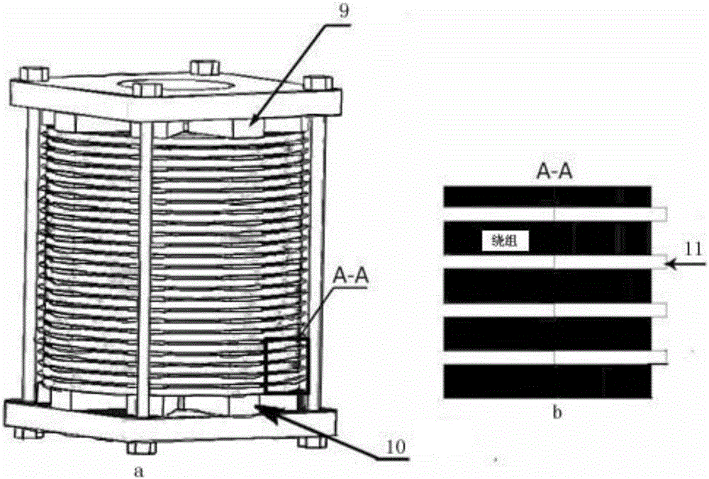
[0027] figure 2 It is a single-phase structure diagram of the transformer winding. In the figure a is the single-phase structure of the transformer winding. The pressure shoe 10 is located at the bottom of the winding to isolate the winding so that it is not directly grounded; the stay 9 is located between the winding and the inner winding and the iron core between the inner and outer windings, the inner winding and the iron core, as the interlayer support and insulation of the winding, and form the heat dissipation oil passage or air passage; the pad 11 is the insulator between the coil and the coil in a single winding, as For support and insulation (as shown in the figure b is the partial AA enlarged schematic diagram of the winding); a slot is longitudinally opened on the stay 9 between the inner winding and the iron core. To the bottom, install the sensors corresponding to the positions of the upper, middle and lower windings respectively. There are 3 stays on each phase...
Embodiment 3
[0032] For the winding online monitoring system, the implementation is as follows:
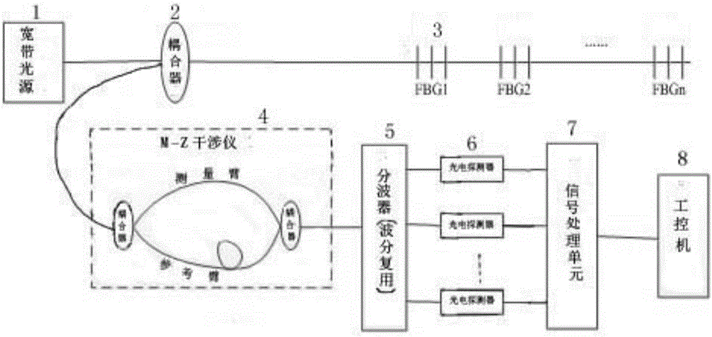
[0033] The winding on-line monitoring system used in the present invention is as figure 1 As shown, it includes: M-Z interferometer, coupler, wave splitter, photodetector, signal processing unit, and industrial computer.
[0034] The broadband light source emits a light wave with a stable bandwidth, which is injected into the optical fiber, and the strain around the quasi-distributed fiber grating sensor changes, so that the wavelength of the reflected light wave changes.
[0035] The coupler couples the reflected waves of different wavelengths into the M-Z interferometer; the M-Z interferometer divides the light into two beams and passes through two arms with different optical paths to complete the interference to obtain interference light.
[0036] The wave splitter divides the interfering light into different lights according to wavelengths and transmits them to the photodetector respectiv...
PUM
 Abstract
Description
Claims
Application Information
 - R&D
- Intellectual Property
- Life Sciences
- Materials
- Tech Scout
- Unparalleled Data Quality
- Higher Quality Content
- 60% Fewer Hallucinations
Browse by: Latest US Patents, China's latest patents, Technical Efficacy Thesaurus, Application Domain, Technology Topic, Popular Technical Reports.
© 2025 PatSnap. All rights reserved.Legal|Privacy policy|Modern Slavery Act Transparency Statement|Sitemap|About US| Contact US: help@patsnap.com


