Liquid crystal display panel and liquid crystal display

A liquid crystal display panel, liquid crystal display technology, applied in the direction of instruments, nonlinear optics, optics, etc., can solve problems such as color shift, light leakage at the boundary of the display area, etc., to achieve the effect of solving light leakage or color shift, and good display quality

Active Publication Date: 2017-05-10
TCL CHINA STAR OPTOELECTRONICS TECH CO LTD
View PDF10 Cites 7 Cited by
  • Summary
  • Abstract
  • Description
  • Claims
  • Application Information

AI Technical Summary

Problems solved by technology

[0005] The invention provides a liquid crystal display panel, which can solve the problems caused by the connection between the common electrode and the metal wiring due to conductive particles and the short circuit caused by the location of the liquid crystal display panel close to the display area, and the arrangement of spacer columns in the non-display area of ​​the array substrate. Technical issues with light leakage or color shift at the border of the display area

Method used


Image

  • Liquid crystal display panel and liquid crystal display
  • Liquid crystal display panel and liquid crystal display

Examples


Embodiment Construction

[0034] The following descriptions of the various embodiments refer to the accompanying drawings to illustrate specific embodiments in which the invention may be practiced. The directional terms mentioned in the present invention, such as [top], [bottom], [front], [back], [left], [right], [inside], [outside], [side], etc., are only for reference The orientation of the attached schema. Therefore, the directional terms used are used to illustrate and understand the present invention, but not to limit the present invention. In the figures, structurally similar elements are denoted by the same reference numerals.

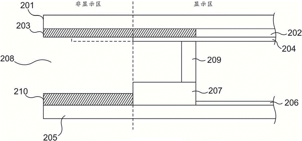
[0035] The present invention is aimed at the existing liquid crystal display panel. Conductive particles are likely to be generated during the bonding process of the color filter substrate and the array substrate, so that the common electrode of the liquid crystal display panel is connected to the metal wiring and short-circuited, and the non-display area is supported b...


PUM


Abstract

The invention provides a liquid crystal display panel. A common electrode is arranged in the manner of being kept away from a projection area formed by projecting metal wires onto a color film substrate, and the intersection area of the common electrode and a projection formed by projecting the metal wires in a non-display area of the array substrate onto the color film substrate is removed through laser cutting. The liquid crystal display panel has the advantages that compared with an existing liquid crystal display panel, the problem that due to conducting particles generated between a common electrode of a liquid crystal display panel and metal wires in a non-display area because of the manufacturing process, short-circuiting occurs can be solved, meanwhile, the technical problem that due to the arrangement of spacing pillars in a non-display area of an array substrate, light leakage or color cast occurs at the boundary of a display area can be solved, and thus better display quality is obtained.

Description

technical field [0001] The invention relates to the field of liquid crystal display technology, in particular to a liquid crystal display panel and a liquid crystal display with the liquid crystal display panel. Background technique [0002] During the lamination process of the color filter substrate and the array substrate of the liquid crystal display panel, conductive particles are often generated in the non-display area of ​​the array substrate. Above the metal traces, the conductive particles generated may electrically connect the common electrodes to the metal traces, resulting in a short circuit between the common electrodes and the metal traces; the prior art is to set spacers between the color filter substrate and the array substrate, The color filter substrate and the array substrate are arranged at intervals, so as to avoid short circuit between the common electrode on the color filter substrate and the metal wiring on the array substrate due to conductive particl...

Claims


Application Information

Patent Timeline
Patent Type & Authority Applications(China)
IPC IPC(8): G02F1/1343G02F1/1345G02F1/1339
CPCG02F1/13394G02F1/134309G02F1/13452G02F2201/121
Inventor 董成才
Owner TCL CHINA STAR OPTOELECTRONICS TECH CO LTD
Why Eureka
Try Eureka