Reactivity control mechanism

A reactivity control and control rod technology, which is applied in the control of nuclear reactions, reactors, and nuclear reactor monitoring, etc., can solve the problems of inability to directly read the linear displacement of control rods, mechanical structure condensation, rod sticking accidents, etc., and achieve easy rod drop time. requirements, continuous and accurate measurement, and the effect of reducing engineering cost

Active Publication Date: 2017-05-10
HEFEI INSTITUTES OF PHYSICAL SCIENCE - CHINESE ACAD OF SCI
View PDF6 Cites 3 Cited by
  • Summary
  • Abstract
  • Description
  • Claims
  • Application Information

AI Technical Summary

Problems solved by technology

For example, in the invention patent "High Temperature Gas-Cooled Reactor Control Rod Driving Mechanism" (public number: 102214487A) filed by the applicant for Tsinghua University, it is proposed to set the ring chain mechanism and the rod position measurement mechanism on the output shaft of the deceleration mechanism. The rotation angle of the rod can be indirectly measured, but the linear displacement of the control rod cannot be directly read, which may lead to large errors
[0006] At the same time, the existing scheme has not considered that during the long-term operation, various vapors (such as lead vapor) in the stack may diffuse to the mechanical structure of the driving mechanism and condense, resulting in rod sticking accidents

Method used


Image

  • Reactivity control mechanism

Examples


Embodiment Construction

[0022] It should be noted that, in the case of no conflict, the embodiments in the present application and the features in the embodiments can be combined with each other. The present invention will be described in detail below with reference to the accompanying drawings and examples.

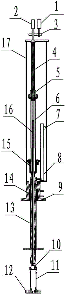
[0023] refer to figure 1 , the structural features of the present invention are described in detail as follows:

[0024] A reactive control mechanism, comprising a spindle motor 1, the spindle motor 1 is connected to a transmission mechanism 4 through a reduction mechanism 3, the transmission mechanism 4 includes a transmission nut 5 and a transmission screw rod, the upper rod end of the transmission screw rod Connected with the rotating shaft of the gripper motor 2, the transmission screw rod cooperates with the transmission nut 5, the drop assembly 6 is arranged on the transmission nut 5, the lower rod end of the transmission screw rod is provided with a push rod 16, and the reduction mechan...


PUM


Abstract

The invention discloses a reactivity control mechanism. The mechanism comprises a spindle motor, a gripper motor, a reducing mechanism, a transmission mechanism, a falling component, a rod position measurement mechanism, a control rod component, a rod falling cushioning mechanism, a balance weight mechanism, a sealing structure, a rod falling executing mechanism, a push rod and a casing, wherein the spindle motor is connected with the reducing mechanism; the transmission mechanism is arranged on an output shaft of the reducing mechanism; the rod position measurement mechanism is meshed with the falling component through a rack; the rod falling executing mechanism is arranged on a connecting piece of the transmission mechanism; the balance weight mechanism is arranged on the falling component; the falling component is cushioned by the rod falling cushioning mechanism at the falling last stage. The reactivity control mechanism drives a set of driving line to move up and down through the spindle motor, the reducing mechanism and the transmission mechanism, and meanwhile prevents various types of high-temperature steam from spreading into the transmission mechanism through the sealing structure.

Description

technical field [0001] The invention relates to the field of nuclear reactor equipment, in particular to a reactivity control mechanism. Background technique [0002] The reactivity control mechanism is the key equipment to achieve effective control of reactivity and safe operation of the reactor, including control rod drive mechanism, control rod assembly, rod position measurement mechanism, and rod drop buffer mechanism, etc. The control rod driving mechanism drives the control rod assembly to move up and down in the core to realize reactive control. In the event of a shutdown accident, the control rod assembly quickly falls into the core under the action of gravity to realize emergency shutdown. [0003] For the liquid heavy metal cooling reactor, one of the important reactor types of the fourth-generation nuclear energy system, the characteristics of the coolant itself pose a huge technical challenge to the realization of the function of the reactivity control mechanism,...

Claims


Application Information

Patent Timeline
Patent Type & Authority Applications(China)
IPC IPC(8): G21C9/02G21C7/12G21C17/10
CPCG21C7/12G21C9/02G21C17/10Y02E30/30
Inventor 吴宜灿郭浩民汪建业宋勇吴庆生
Owner HEFEI INSTITUTES OF PHYSICAL SCIENCE - CHINESE ACAD OF SCI
Why Eureka
Try Eureka