Entrance-exit control circuit

A technology for controlling circuits, entrances and exits, applied in program control, computer control, general control systems, etc., can solve the problems of increasing assembly space, increasing fault points, unfavorable installation, etc., to reduce assembly space, improve overall performance, and facilitate installation The effect of maintenance

Inactive Publication Date: 2017-05-10
SHENZHEN DOOR INTELLIGENT CONTROL TECH
View PDF11 Cites 0 Cited by
  • Summary
  • Abstract
  • Description
  • Claims
  • Application Information

AI Technical Summary

Problems solved by technology

The current method is to add a network switch to the control equipment, which increases the cost, increases the assembly space, is not conducive to installation, and increases the point of failure

Method used


Image

  • Entrance-exit control circuit
  • Entrance-exit control circuit
  • Entrance-exit control circuit

Examples


Embodiment Construction

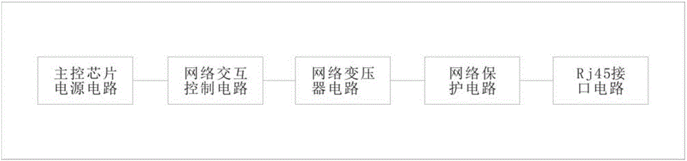
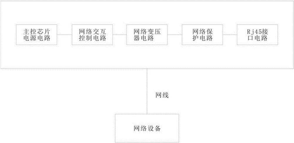
[0021] Please also refer to figure 1 and figure 2 , as shown in the figure, the entrance and exit control circuit includes a main control board circuit, and the main control board circuit further includes a network interactive control circuit with a main control chip, a network transformer circuit, a network protection circuit, an RJ45 interface circuit and a main control board The chip power supply circuit, the network interactive control circuit is electrically connected with the network transformer circuit, the network transformer circuit is electrically connected with the network protection circuit, and the network protection circuit is electrically connected with the RJ45 interface circuit; the network interactive control circuit further includes a main control chip The internal voltage compensation circuit, the clock circuit, the working instruction circuit, the filter circuit, the reset circuit and the impedance matching circuit are electrically connected, and the netw...


PUM


Abstract

The invention discloses an entrance-exit control circuit comprises a main control board circuit. The main control board circuit comprises a network interaction control circuit having a main control chip, a network transformer circuit, a network protection circuit, an RJ45 interface circuit and a main control chip power source circuit, the network interaction control circuit is electrically connected with the network transformer circuit which is electrically connected with the network protection circuit, and the network protection circuit is electrically connected with the RJ45 interface circuit; the network interaction control circuit further comprises an internal voltage compensation circuit, a clock circuit, a working indication circuit, a filter circuit, a resetting circuit and an impedance matching circuit which are electrically connected with the main control chip, and the network transformer circuit is connected with the impedance matching circuit. The main control chip is made to directly control a network switchboard chip, multiple RJ45 interfaces are provided, and network switchboard equipment in the middle is removed, so that cost is lowered, assembly space is reduced, wiring is simple, convenience is brought to mounting and maintaining, and overall performance of equipment is improved.

Description

technical field [0001] The invention mainly relates to an entrance and exit control circuit. Background technique [0002] In the entrance and exit control equipment, in order to realize the safety management and control of people or vehicles, it is necessary to adopt multiple methods for management and control, and a network of various equipment is jointly formed. In the field of parking lot control, vehicle control needs to adopt methods such as license plate recognition or card detection, and assist network intercom and video surveillance, etc., and all devices are connected through TCP / IP. The current method is to add a network switch to the control equipment, which increases the cost, increases the assembly space, is not conducive to installation, and increases the point of failure. Contents of the invention [0003] The technical problem to be solved by the present invention is to provide an entrance and exit control circuit in order to overcome the above-mentioned ...

Claims


Application Information

Patent Timeline
Patent Type & Authority Applications(China)
IPC IPC(8): H04L12/02H04L29/08G05B19/042
CPCG05B19/0423H04L12/02H04L67/12
Inventor 谭明凤蔡昌贵黄碧华姚云鹏胡佳奇
Owner SHENZHEN DOOR INTELLIGENT CONTROL TECH
Why Eureka
Try Eureka