Video playing control method and device

A control method and panoramic video technology, applied in the multimedia field, can solve serious, high consumption, video freeze and other problems

Active Publication Date: 2017-05-10
SUPERD CO LTD
View PDF7 Cites 11 Cited by
  • Summary
  • Abstract
  • Description
  • Claims
  • Application Information

AI Technical Summary

Problems solved by technology

[0007] The purpose of the present invention is to provide a method and device for controlling video playback, so as to s

Method used


Image

  • Video playing control method and device
  • Video playing control method and device
  • Video playing control method and device

Examples


no. 1 example

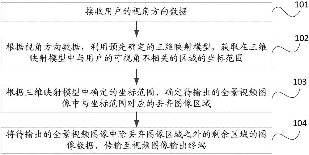
[0240] Such as figure 1As shown, it is a flow chart of the steps of the video playback control method in the first embodiment of the present invention. The control method is applied to the server side, including:

[0241] Step 101, receiving viewing direction data of a user.

[0242] In this step, the server end may receive viewing angle direction data transmitted in real time by the video image output terminal. Specifically, the view direction data may be gyroscope data, and the gyroscope data may be used to indicate the user's viewing posture, that is, to indicate the user's view direction. In this way, when the server receives the gyroscope data transmitted by the video image output terminal in real time, it can obtain the user's view direction data in real time.

[0243] Step 102 , according to the view direction data, using a predetermined 3D mapping model, to obtain a coordinate range of an area in the 3D mapping model that is not related to the user's viewing angle. ...

no. 2 example

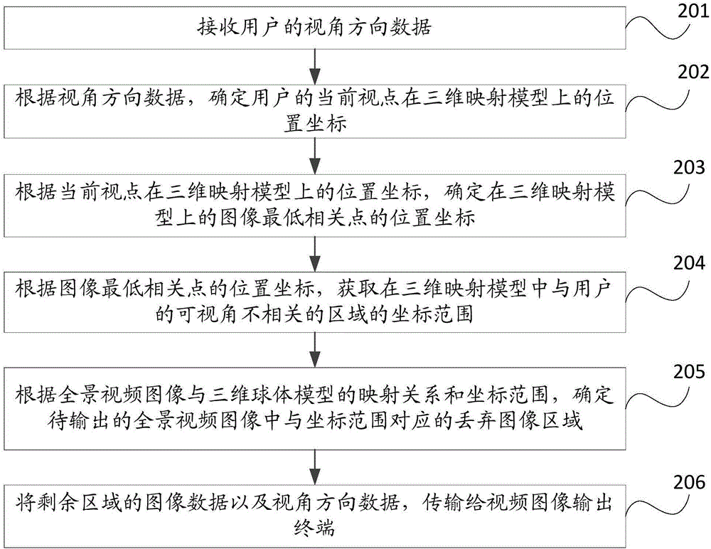
[0251] Such as figure 2 As shown, it is a flow chart of the steps of the video playback control method in the second embodiment of the present invention. The control method is applied to the server side, including:

[0252] Step 201, receiving viewing direction data of a user.

[0253] In this step, the server end may receive viewing angle direction data transmitted in real time by the video image output terminal. Specifically, the view direction data may be gyroscope data, and the gyroscope data may be used to indicate the user's viewing posture, that is, to indicate the user's view direction. In this way, when the server receives the gyroscope data transmitted by the video image output terminal in real time, it can obtain the user's view direction data in real time.

[0254] Step 202: Determine the position coordinates of the user's current viewpoint on the three-dimensional mapping model according to the view direction data.

[0255] In this step, specifically, the user...

no. 3 example

[0360] Such as Figure 11 As shown, it is a flow chart of the steps of the video playback control method in the third embodiment of the present invention. The control method is applied to the video image output terminal, including:

[0361] Step 1101, acquire the viewing angle direction data of the user in real time, and send the viewing angle direction data to the server.

[0362] In this step, specifically, the viewing direction data of the user may be gyroscope data, and the viewing direction data may be used to indicate the viewing posture of the user, that is, to indicate the viewing direction of the user. Therefore, the video image output terminal can obtain the user's viewing angle direction data through the gyroscope, and after the video image output terminal obtains the user's viewing angle direction data in real time, it can send the viewing angle direction data to the server.

[0363] Step 1102, receiving the image data of the remaining area except the discarded im...


PUM


Abstract

The invention provides a video playing control method and device. The control method applied to a server side comprises the steps of receiving angle of view direction data of a user; obtaining a coordinate range of a region irrelative to an angle of view of a user through utilization of a predetermined three-dimensional mapping model according to the angle of view direction data of the user, wherein the region is in the three-dimensional mapping model; determining a discarded image region corresponding to the coordinate range in a to-be-output panoramic video image according to the determined coordinate range in the three-dimensional mapping model; and transmitting the image data of the residual region in the to-be-output panoramic video image except the discarded image region to a view image output terminal. According to the embodiment of the method and the device, the problem that in the prior art, either the consumption is relatively high or a video is delayed relatively seriously when a panoramic video is played is solved.

Description

technical field [0001] The present invention relates to the field of multimedia technology, in particular to a method and device for controlling video playback. Background technique [0002] When performing virtual reality (VR, Virtual Reality) or 360-degree panoramic video live broadcast, the live broadcast picture can be changed correspondingly according to the user's perspective. However, usually, the picture viewed by the user at one moment has only a certain angle, and the angle is generally within the range of 80 to 110 degrees between the horizontal field of view and the vertical field of view, that is to say, the picture viewed by the user at one moment It only occupies a small part of the 360-degree panoramic image, and the occupied part is about 1 / 8 to 1 / 6 of the 360-degree panoramic image, while other parts of the 360-degree image are invisible at the same time. [0003] At present, the following two methods are usually used in the prior art for VR or 360-degree ...

Claims


Application Information

Patent Timeline
IPC IPC(8): H04N13/02H04N13/04H04N21/431H04N21/454H04N21/472H04N21/485H04N21/81G06T5/00G06T15/10
CPCG06T5/008G06T15/10H04N13/275H04N13/366H04N21/4312H04N21/4542H04N21/47205H04N21/4854H04N21/8146
Inventor 田志泽
Owner SUPERD CO LTD
Why Eureka
Try Eureka