Magnetic resonance imaging device, and magnetic resonance imaging method

A magnetic resonance imaging and magnetic field technology, applied in the direction of measuring devices, measuring magnetic variables, medical science, etc., can solve problems such as diagnosis obstacles, and achieve the effect of suppressing sharp artifacts

Inactive Publication Date: 2017-05-10
HITACHI LTD
View PDF4 Cites 6 Cited by
  • Summary
  • Abstract
  • Description
  • Claims
  • Application Information

AI Technical Summary

Problems solved by technology

[0003] In the spin echo (SpinEcho) imaging of the sagittal (SAG) and coronal (COR) sections where the Z-axis is set in the phase encoding direction, sharp artifacts often occur, which may hinder diagnosis

Method used


Image

  • Magnetic resonance imaging device, and magnetic resonance imaging method
  • Magnetic resonance imaging device, and magnetic resonance imaging method
  • Magnetic resonance imaging device, and magnetic resonance imaging method

Examples


no. 1 approach >

[0049] Hereinafter, examples of embodiments of the present invention will be described in detail with reference to the drawings. In addition, in all the drawings for explaining the embodiments of the invention, components having basically the same functions are denoted by the same reference numerals, and overlapping descriptions are omitted.

[0050] [Block Diagram of MRI Apparatus]

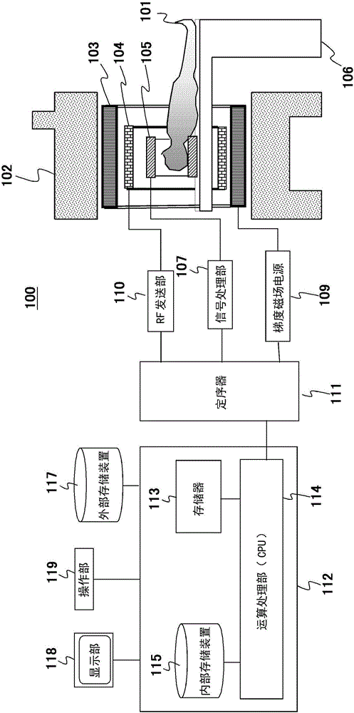
[0051] First, the MRI apparatus of this embodiment will be described. figure 1 It is a block diagram showing the overall configuration of an example of the MRI apparatus 100 of the present embodiment. The MRI apparatus 100 of this embodiment is an apparatus for obtaining a tomographic image of the subject 101 by using the NMR phenomenon, such as figure 1 As shown, it includes: a static magnetic field generating source 102, a gradient magnetic field coil 103, a gradient magnetic field power supply 109, a high-frequency magnetic field (RF) transmitting coil 104, an RF transmitting section 110, an...

no. 2 approach >

[0195] Next, a second embodiment of the present invention will be described. In the first embodiment, by setting the number of repetitions NSA to an even number, alternately performing measurements in which the polarities of the CASD gradient magnetic fields (323odd, 323evn) are reversed, and adding them together, suppression of deformation from the magnetic field is obtained. An image of the echo signal at the location. On the other hand, in this embodiment, an image in which the echo signal from the magnetic field deformation position is suppressed is obtained based on the primary measurement result. Therefore, it is applicable even if the number of repetitions NSA is an odd number.

[0196] The MRI apparatus of this embodiment is basically the same as the MRI apparatus 100 of the first embodiment. Among them, the structure of the CAS sequence followed by the measuring unit 130 is different. Hereinafter, this embodiment will be described focusing on configurations differe...


PUM


Abstract

In order to suppress cusp artifacts at known positions where magnetic field distortion occurs, irrespective of imaging conditions such as slice thickness and field of view (FOV), in a sequence in which irradiation with a plurality of refocus radio frequency (RF) pulses is performed after one excitation RF pulse, a micro dephasing gradient magnetic field, which induces, between the excitation RF pulse and the first refocus RF pulse, a phase shift in the transverse magnetization at the aforementioned positions, is applied in the phase-encoding direction and / or the slice-encoding direction. As a result, signal values of nuclear magnetic resonance (NMR) signals (echo signals) at the aforementioned positions are suppressed, and cusp artifacts are reduced.

Description

technical field [0001] The present invention relates to magnetic resonance imaging (hereinafter referred to as MRI) technology, in particular to a technology for suppressing artifacts (Artifact) generated due to inhomogeneous static magnetic field and non-linear gradient magnetic field. Background technique [0002] Among the horizontal magnetic field MRI apparatuses, the mainstream is a short gantry type MRI apparatus in which the Z-axis (magnetic field direction) length of the gantry is shortened in order to emphasize the sense of openness of the subject. However, in the short gantry type MRI apparatus, since the static magnetic field uniform space and the gradient magnetic field linear region are narrow, the magnetic field at the end of the gantry is deformed. Due to the influence of magnetic field deformation outside the photographic FOV, high-brightness bright spots or crescent-shaped artifacts will be generated in the photographic FOV. It is called CuspArtifact. [0...

Claims


Application Information

Patent Timeline
Patent Type & Authority Applications(China)
IPC IPC(8): A61B5/055
CPCA61B5/055G01R33/5617G01R33/56563G01R33/56572G01R33/387G01R33/5659
Inventor 平井甲亮
Owner HITACHI LTD
Why Eureka
Try Eureka