
Excavation tool

A tool and drill bit technology, applied in the field of double-pipe excavation tools, can solve the problems of decreased drilling performance, enlarged diameter drill bit, large load, etc., and achieves the effect of reducing construction costs

Inactive Publication Date: 2017-05-10
MITSUBISHI MATERIALS CORP
View PDF9 Cites 11 Cited by
  • Summary
  • Abstract
  • Description
  • Claims
  • Application Information

AI Technical Summary

Problems solved by technology

However, when the expansion drill is retracted after the excavation is completed, and each shank device is recovered, there is a limit to increasing the expansion drill, and when forming an excavation hole with a large inner diameter, the load is large, and it is also possible to support the expansion drill rotatably. shaft damage
In addition, the setting amount of the digging blade provided on the expanding drill bit is also limited, and the larger the diameter of the digging hole, the lower the drilling performance.

Method used


Image

  • Excavation tool
  • Excavation tool
  • Excavation tool

Examples


Embodiment Construction

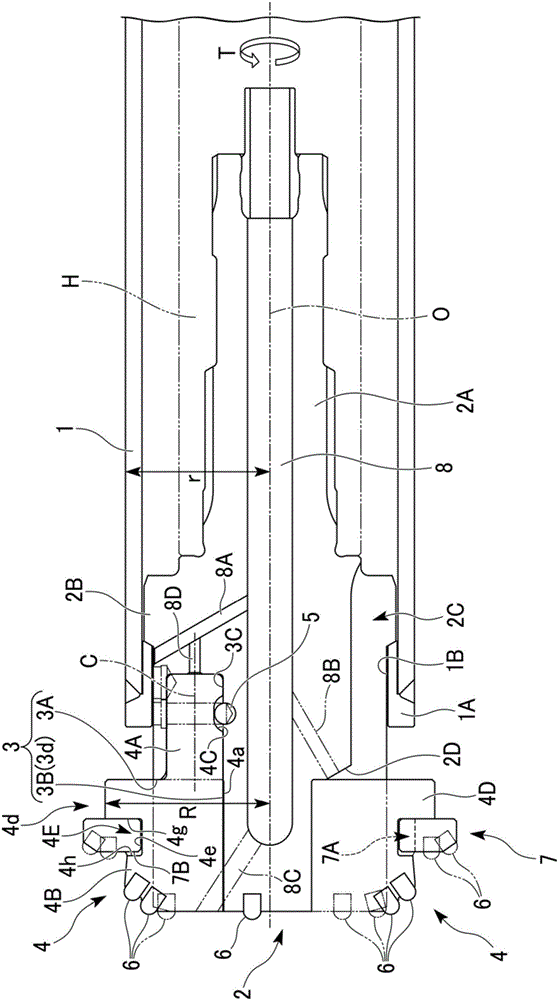
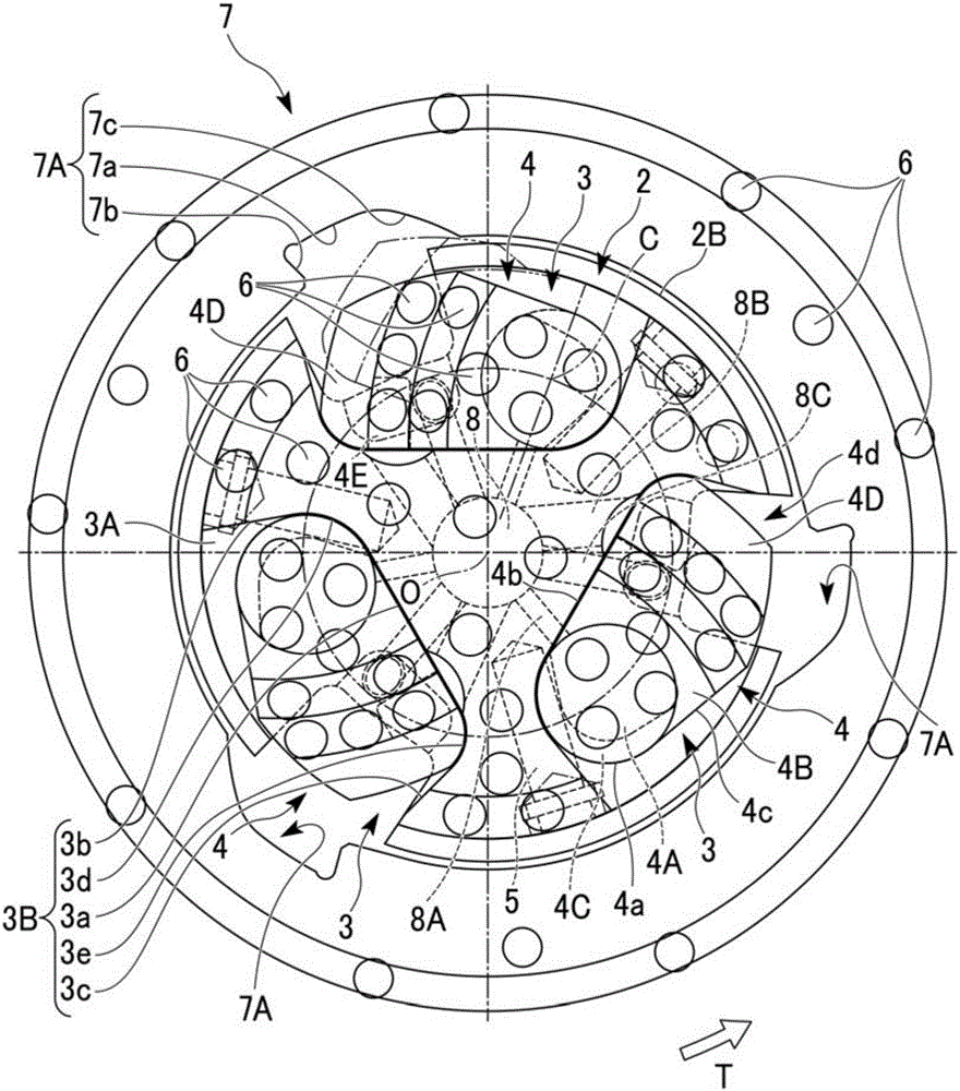
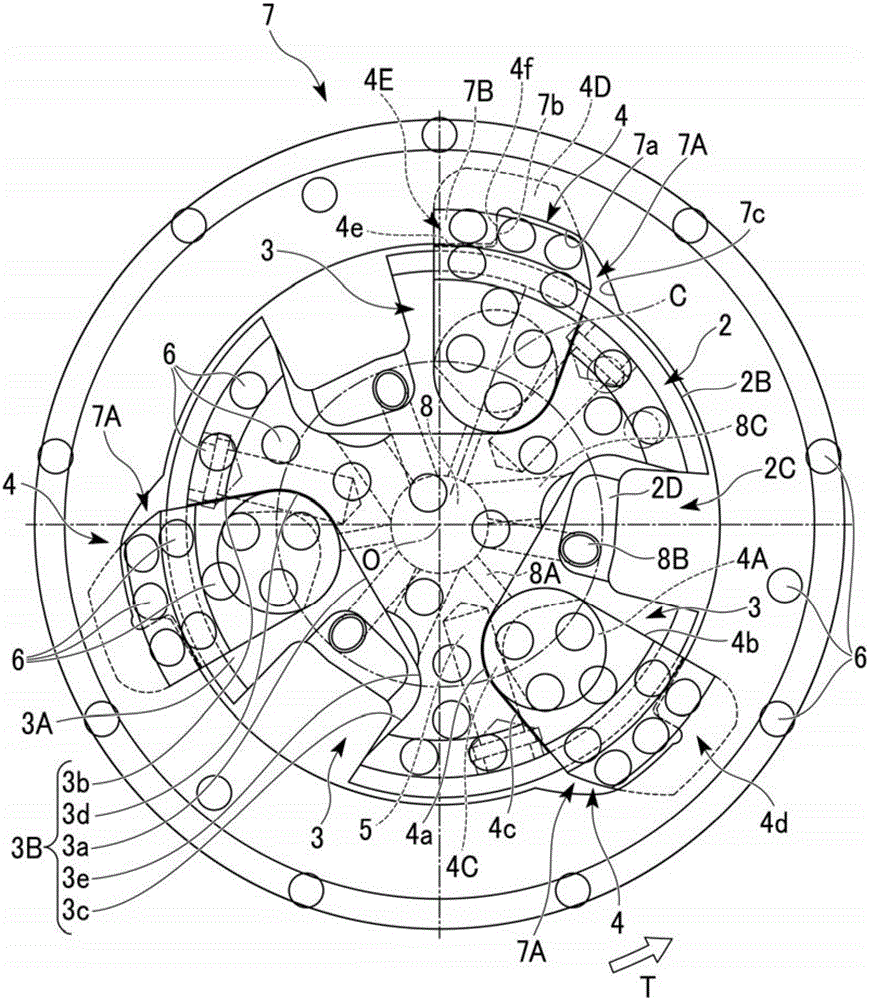
[0026] Figure 1 to Figure 5 It is a figure which shows one embodiment of the digging tool of this invention. In this embodiment, the bushing 1 is formed of a metal material such as steel into a cylindrical shape centered on the axis O, and at the front end of the bushing 1 ( figure 1 The left side part in ) is equipped with a sleeve top 1A which is also formed into a multi-stage cylindrical shape from a metal material such as steel.

[0027] The inner diameter of the sleeve top 1A is set to a constant inner diameter smaller than the inner diameter of the sleeve 1, and the outer diameter of the front end is set to be the same as the outer diameter of the sleeve 1, and the outer diameter of the rear end is set to be inserted into the The size of casing 1. The sleeve top 1A is integrated with the sleeve 1 so as to be coaxial with the sleeve 1 by fitting in the rear end portion of the sleeve top 1A from the front end side of the sleeve 1 and joining by welding or the like.

[...


PUM


Abstract

This excavation tool comprises: a casing pipe, a large-diameter ring bit disposed coaxially on a distal end side of the casing pipe, and a pilot bit inserted into the ring bit through the inside of the casing pipe. A bit head that expands in diameter when rotated in a tool rotation direction during excavation is provided to an outer circumferential part at the distal end of the pilot bit. Provided to the ring bit are: an engaging part that engages with the expanded bit head in the tool rotation direction and a first abutting part capable of abutting the bit head in the axial direction.

Description

technical field [0001] The present invention relates to a so-called double-tube excavating tool for digging with a ring drill disposed on the front end side of a casing and a pilot drill inserted into the casing. [0002] This application claims priority based on Patent Application No. 2014-167602 for which it applied in Japan on August 20, 2014, and uses the content here. Background technique [0003] As such a double-pipe excavating tool, Patent Document 1 proposes an excavating tool in which a ring drill bit is rotatably inserted into the front end of the casing so that the inner and outer peripheral surfaces thereof face each other, and a drill bit inserted into the casing An inner drill is attached to the front end of the transmission member, and the impact force and thrust are transmitted to the casing through the inner drill, and the other rotational force is transmitted to the ring drill to perform drilling. After forming an excavation hole up to a specified depth, ...

Claims


Application Information

Patent Timeline
Patent Type & Authority Applications(China)
IPC IPC(8): E21B10/32
CPCE21B10/327E21B10/627
Inventor 中村和由高月裕贵
Owner MITSUBISHI MATERIALS CORP
Learn More