
Roller feeding device

A roller and lifting device technology, which is applied in the field of roller feeding devices, can solve problems such as unsmooth feeding, easy scratching of rollers, and affecting the appearance quality of rollers, so as to achieve smooth feeding and no damage to the feeding Effect

Pending Publication Date: 2017-05-17
KUNSHAN AODELU AUTOMATION TECH
View PDF5 Cites 2 Cited by
  • Summary
  • Abstract
  • Description
  • Claims
  • Application Information

AI Technical Summary

Problems solved by technology

Although the current feeding mechanism, such as the disk feeding mechanism, solves the process of products from disorder to order, it is easy to scratch the surface of the roller during feeding, which affects the appearance quality of the roller; in addition, the existing The feeding mechanism relies on the gravity of the roller to slide down when loading materials, resulting in unsmooth feeding, which seriously affects the normal operation of subsequent equipment

Method used


Image

  • Roller feeding device

Examples


Embodiment Construction

[0019] The technical solutions of the present invention will be further described below with reference to the accompanying drawings and through specific embodiments.

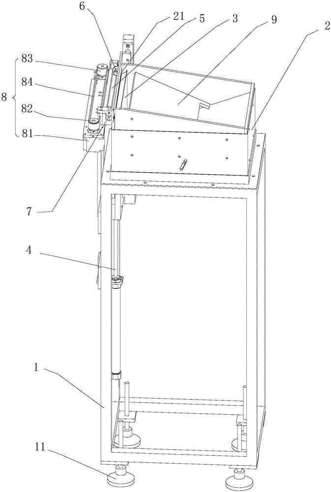
[0020] like figure 1 As shown, a roller feeding device includes a frame 1, and the top of the frame 1 is fixedly connected with a silo 2; the side top of the silo 2 is provided with a discharge port 21, and the height direction of the discharge port 21 can only be Through a roller; the side of the outlet 21 facing the silo 2 is provided with a jacking mechanism, which lifts up the roller in the silo 2, and the roller moves vertically upward along one side of the silo 2 To the discharge port 21; the other side of the discharge port 21 is connected with the material channel 5 for receiving the rollers; it also includes a dial connected to the frame 1 and used to pull the rollers in the material channel 5 away from the material channel 5 material organization.

[0021] The roller feeding device proposed by the pr...


PUM


Abstract

The invention discloses a roller feeding device. The roller feeding device comprises a rack. A stock bin is fixedly connected to the top of the rack. A discharging opening is formed in the side top of the stock bin. Only one roller can pass through the discharging opening in the height direction. A material jacking mechanism is arranged on the side, facing the stock bin, of the discharging opening. The material jacking mechanism jacks the roller in the stock bin upwards. The roller moves vertically and upwards to the discharging opening along one side of the stock bin. The other side of the discharging opening is connected with a material passageway for receiving the roller. The roller feeding device further comprises a material poking mechanism for poking the roller in the material passageway away from the material passageway. By the adoption of the roller feeding device, rollers can be fed in order without damage, and feeding is smooth.

Description

technical field [0001] The invention relates to the technical field of roller conveying, in particular to a roller feeding device. Background technique [0002] Cylindrical rollers are placed in a disordered state, and are usually loaded by a feeding device. Although the current feeding mechanism, such as the disk feeding mechanism, solves the process of products from disorder to order, it is easy to scratch the surface of the roller during feeding, which affects the appearance quality of the roller; in addition, the existing When the feeding mechanism is feeding, it relies on the gravity of the roller to slide down, resulting in unsmooth feeding, which seriously affects the normal operation of the downstream equipment. Contents of the invention [0003] The purpose of the present invention is to provide a roller feeding device, which can realize the orderly and non-damaging feeding of the rollers, and the feeding is smooth. [0004] For this purpose, the present inventi...

Claims


Application Information

Patent Timeline
IPC IPC(8): B65G47/82B65G47/74
CPCB65G47/74B65G47/82
Inventor 郁彬
Owner KUNSHAN AODELU AUTOMATION TECH
Learn More