
a leaf blower

A leaf blower and machine body technology, applied in road cleaning, construction, cleaning methods, etc., can solve the problems of complex structure of the air volume adjustment device, affecting the effect of blowing leaves, inconvenient use or maintenance, etc., to improve grip comfort, structure Simple, easy to use and reliable results

Active Publication Date: 2018-08-28
NINGBO KINGBIRD POWER TOOLS
View PDF6 Cites 3 Cited by
  • Summary
  • Abstract
  • Description
  • Claims
  • Application Information

AI Technical Summary

Problems solved by technology

A part of the leaf blower in the prior art is to increase or decrease the wind speed by changing the speed of the motor, which is a waste of time and electric energy; The way to increase the wind speed is to reduce the cross-sectional area of ​​the blower port, so that the airflow density passing through the unit area will increase, and the wind speed will also increase thereupon. Another part of the leaf blower in the prior art utilizes this point, and the air blower is equipped with There are many blowing pipes with different calibers, but due to too many accessories, it is inconvenient to use the leaf blowers that are often used outdoors; there are still some leaf blowers in the prior art that increase the air volume adjustment at the air outlet of the blowing pipe Assemblies, but the air volume adjustment device in the prior art is integrated with the blower pipe. If the air volume adjustment device breaks down, it will affect the use of the entire leaf blower, and the air volume adjustment device in the prior art has a complex structure, which is difficult to use or maintain. Inconvenient
[0003] In addition, the inner wall surface of the blowing pipe of the leaf blower in the prior art is always parallel to its longitudinal axis, so that the air flow is easy to concentrate on the center of the inner wall, resulting in uneven wind speed blown through the blowing pipe, which is easy to form a blowout phenomenon and affects the blowing of leaves. Effect

Method used


Image

  • a leaf blower
  • a leaf blower
  • a leaf blower

Examples


Embodiment Construction

[0027] In order to have a further understanding and understanding of the structural features of the present invention and the achieved effects, the preferred embodiments and accompanying drawings will be used for a detailed description, as follows:

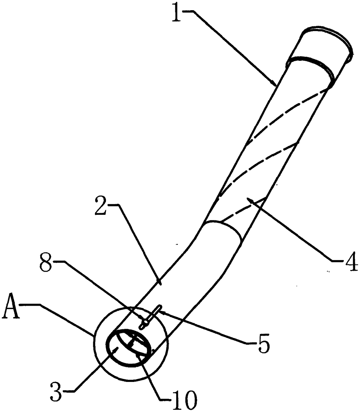
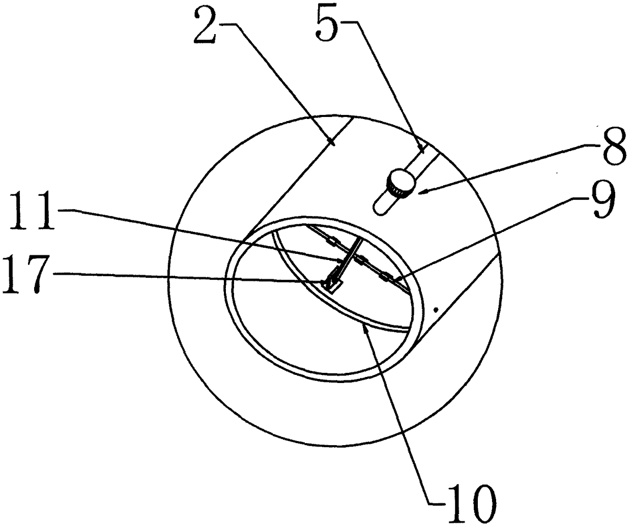
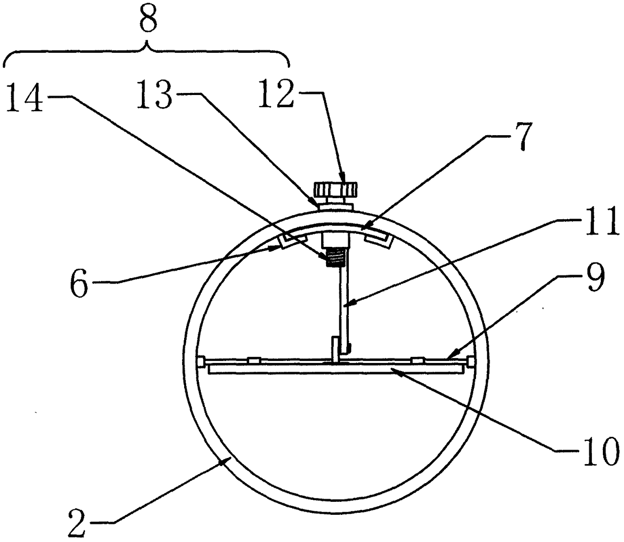
[0028] Such as Figure 1 to Figure 2 Shown, a kind of leaf blower comprises a body (not shown in the figure) with blowing function, a hollow blowpipe 1 connected to the body at one end, the wind blown out of the body passes through the blowpipe 1, as an improvement of the present invention, the blowpipe The air outlet end of 1 is provided with a blowing nozzle 2, and the blowing nozzle 2 is provided with an adjusting device 3 for adjusting the air volume. When using the leaf blower, the area and shape of the air outlet end of the blowing nozzle 2 can be easily adjusted to change the blowing speed. Easy to use; at least two helical curved surfaces 4 extending from the air inlet end to the air outlet end and intertwined are provided...


PUM


Abstract

The invention relates to the field of garden electric tools and provides a leaf blower, comprising a body with blowing function and a hollow blow pipe with one end connected to the body; air blown from the body passes through the blow pipe. The leaf blower is characterized in that the outflow end of the blow pipe is provided with a nozzle, the nozzle is provided with an adjusting device for the adjustment of air volume, the inner wall of the blow pipe is provided with at least two spiral surfaces extended from the inflow end to the outflow end and tangled together, and a flow of air flows spirally along the spiral surfaces in the blow pipe. The blowing speed of the leaf blower provided herein can be adjusted by adjusting rotational angle of an air adjusting plate; the adjusting device is simple in structure and convenient and reliable to use; outflow stability can be improved significantly, and leaf blowing effect of the leaf blower can be improved; vibrations are decreased, and user experience on operation is improved.

Description

technical field [0001] The invention relates to the field of garden electric tools, in particular to a leaf blower. Background technique [0002] Leaf blowers are widely used in the field of garden power tools, mainly to blow leaves, grass clippings, branches and other garbage on the ground into a pile by blowing air, so as to facilitate subsequent processing and reduce the burden on users. However, the existing leaf blowers can only blow away light debris. In daily life, fallen leaves and other debris tend to fall into wet and narrow areas. These debris will not be blown away by ordinary blowing. Therefore need to improve the wind speed of leaf blower when blowing. A part of the leaf blower in the prior art is to increase or decrease the wind speed by changing the speed of the motor, which is a waste of time and electric energy; The way to increase the wind speed is to reduce the cross-sectional area of ​​the blower port, so that the airflow density passing through the un...

Claims


Application Information

Patent Timeline
Patent Type & Authority Patents(China)
IPC IPC(8): E01H1/08
CPCE01H1/0809
Inventor 李咸进王小强
Owner NINGBO KINGBIRD POWER TOOLS
Learn More