An improved telescopic movable chute

A mobile and improved technology, applied in the field of pouring concrete, can solve the problems of low pouring efficiency, waste of concrete, high labor intensity of workers, etc.

Active Publication Date: 2018-11-06
平邑经济开发区投资发展有限公司
View PDF5 Cites 0 Cited by
  • Summary
  • Abstract
  • Description
  • Claims
  • Application Information

AI Technical Summary

Problems solved by technology

[0002] At present, when pouring concrete on the ground or on the road in the field of construction engineering, the concrete is poured directly to the ground by the concrete tank truck, and the workers then use the target to pick up the concrete to the pouring point. Raking the rake to a distance not only reduces the efficiency of pouring, but also increases the labor intensity of the workers and wastes concrete

Method used


Image

  • An improved telescopic movable chute
  • An improved telescopic movable chute
  • An improved telescopic movable chute

Examples


Embodiment Construction

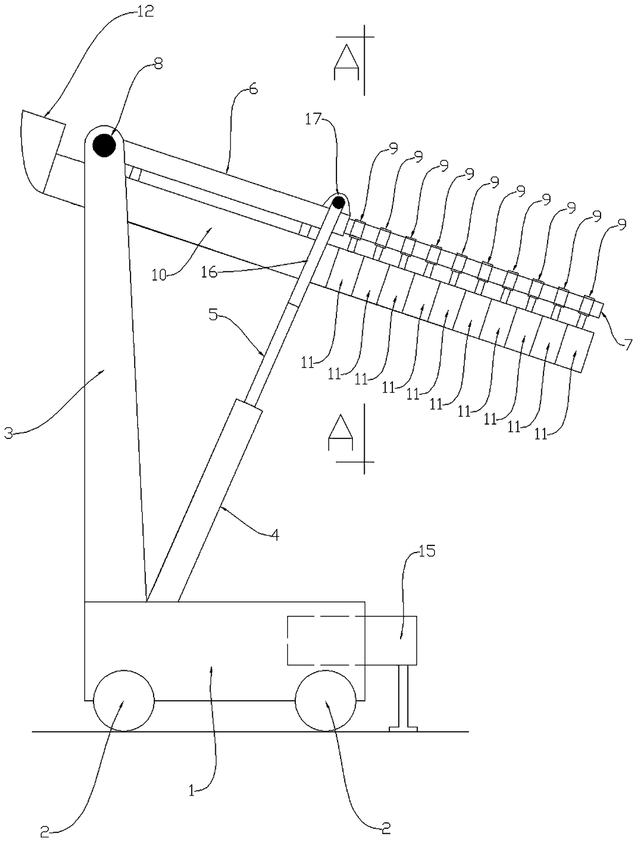
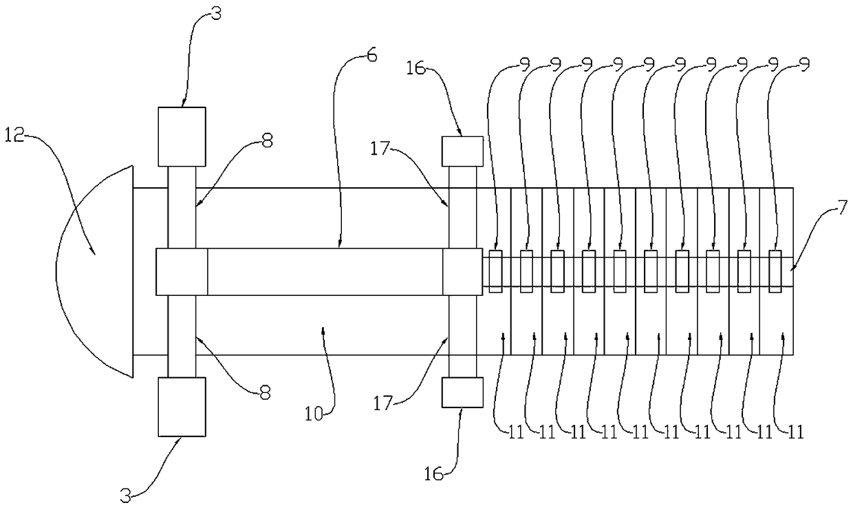
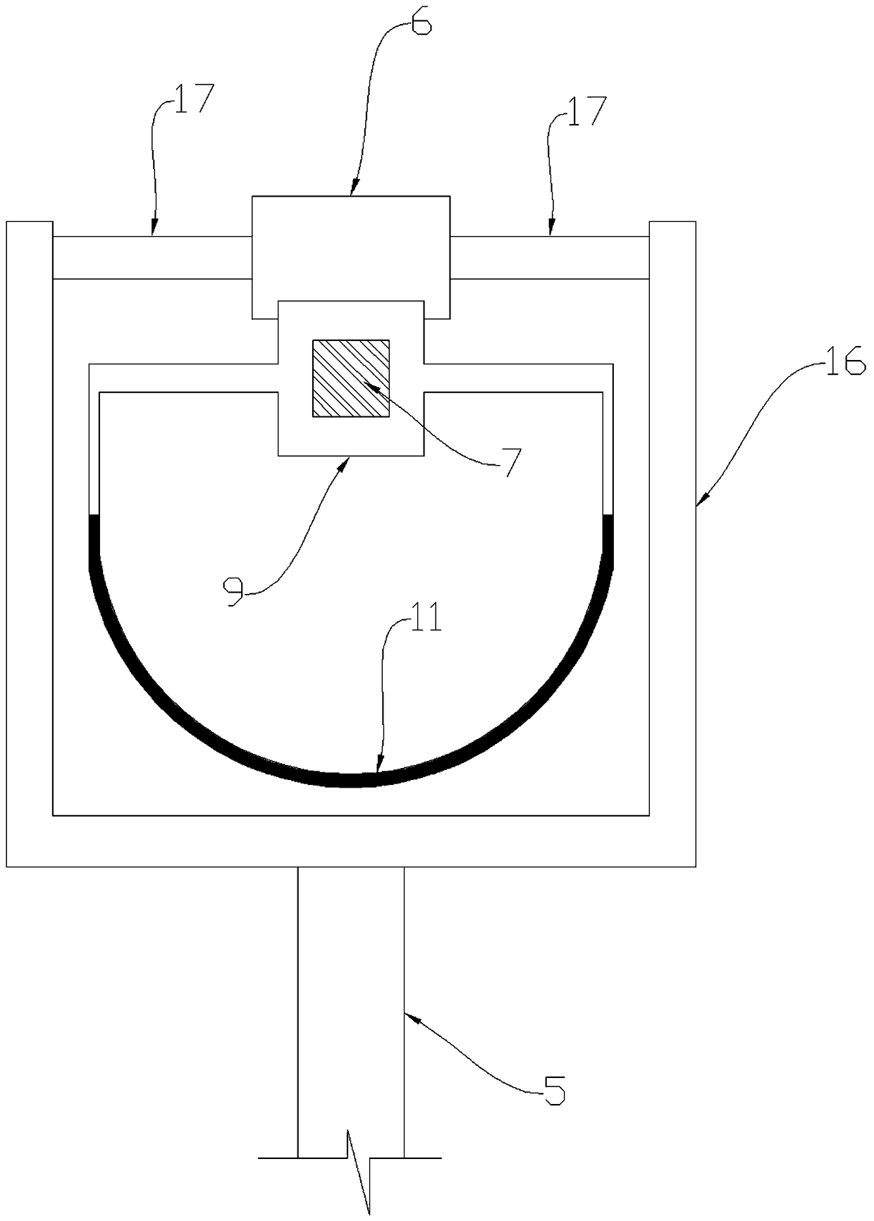
[0011] The content of the invention has described the specific implementation of the present invention in detail, and will not repeat it here; it needs to be explained: 1. The shaft section of the telescopic rod 7 matches the hole 13, and the shaft section of the telescopic rod 7 is either square or elliptical shape, or any shape other than a circle, because if the shaft section of the telescopic rod 7 is circular, the hole 13 of the movable frame 9 can rotate around the telescopic rod 7; two, the present invention is an applied for patent " A telescopic mobile chute”, application number: 2017100821172 improved version, it designs the arm (6) and the telescopic rod (7) above the chute, avoiding the influence of the concrete dripping in the movable chute 11 on the telescopic rod 7 Defects in normal operation, at the same time, the hydraulic cylinder 4 is arranged at the left end of the vehicle frame 1, which increases the anti-overturning moment of the vehicle body. In addition,...


PUM


Abstract

The invention discloses an improved type telescopic movable chute tube. The improved type telescopic movable chute tube is mainly used for pouring concrete in the field of constructional engineering. The improved type telescopic movable chute tube is high in pouring efficiency, concrete is saved, and the labor intensity is relieved. The improved type telescopic movable chute tube mainly comprises a vehicle frame, wheels, an n-shaped vertical frame, a hydraulic cylinder, a hydraulic piston, a telescopic rod, a movable frame, a fixed chute tube body, movable chute tube bodies, a feed hopper, a front support device and an n-shaped frame. According to the main working principle of the improved type telescopic movable chute tube, the concrete slides over the fixed chute tube body and the multiple movable chute tube bodies from top to bottom, slides out from the movable chute tube body at the most front end and enters a pouring point; if the concrete needs to be poured to a far place, the telescopic rod is stretched rightwards, the front end of the telescopic rod drives the movable chute tube body at the most front end to move frontwards, after a limiting ring of the movable chute tube body at the most front end touches a limiting ring of the second section of movable chute tube body, the second section of movable chute tube body is pulled out, and in the same way, the rest sections of movable chute tube bodies are pulled out; and the hydraulic piston is stretched out or retracted, and the inclined angle of concrete discharge and the discharge height can be changed.

Description

technical field [0001] The invention is mainly used for pouring concrete in the field of construction engineering. Background technique [0002] At present, when pouring concrete on the ground or on the road in the field of construction engineering, the concrete is poured directly to the ground by the concrete tank truck, and the workers then use the target to pick up the concrete to the pouring point. If the rakes are pulled far away, not only the pouring efficiency is low, the labor intensity of the workers is high, and the concrete is wasted. Contents of the invention [0003] The present invention solves the above-mentioned problems. It not only has high pouring efficiency, saves concrete, but also reduces the labor intensity of workers; 4), hydraulic piston (5), arm (6), telescopic rod (7), shaft A (8), movable frame (9), fixed chute (10), movable chute (11), feed hopper ( 12), the front support device (15), the portal frame (16), and the shaft B (17); the frame (1)...

Claims


Application Information

Patent Timeline
Patent Type & Authority Patents(China)
IPC IPC(8): E04G21/04
CPCE04G21/0481
Inventor 彭宝安
Owner 平邑经济开发区投资发展有限公司
Why Eureka
Try Eureka