A low-infrared radiation signal exhaust nozzle and its infrared suppression method

A technology of infrared radiation and exhaust nozzles, which is applied in jet propulsion devices, machines/engines, mechanical equipment, etc., can solve the problems of reducing exhaust temperature, reducing infrared radiation characteristics, and complex structure, so as to reduce radiation and reduce infrared Effects of Radiated Signals

Inactive Publication Date: 2018-02-06
NANJING UNIV OF AERONAUTICS & ASTRONAUTICS
View PDF5 Cites 0 Cited by
  • Summary
  • Abstract
  • Description
  • Claims
  • Application Information

AI Technical Summary

Problems solved by technology

The second-generation infrared suppression device is still an add-on or optional part of the engine, and is subject to too many constraints in shape and size. Although it reduces the temperature of hot components and exhaust exhaust to a certain extent, it is necessary to reduce the temperature by 3~ The infrared radiation feature in the 5mm band has a significant effect, but compared to the fuselage, its exposed shield and exhaust tail flame are still high-temperature hotspots displayed as point sources, and it is very difficult to further eliminate the infrared radiation influence of the engine exhaust device
The cooling air is inhaled through the air inlet above the tail boom, mixed with the hot exhaust from the engine, and then discharged through the downward gaps on both sides of the tail boom, and then blown away by the downwash of the rotor, so that the exhaust temperature is significantly reduced, but this This kind of infrared suppression device has complex structure, and changes the overall structure of the helicopter greatly, which is not conducive to the modification of existing helicopters

Method used


Image

  • A low-infrared radiation signal exhaust nozzle and its infrared suppression method
  • A low-infrared radiation signal exhaust nozzle and its infrared suppression method
  • A low-infrared radiation signal exhaust nozzle and its infrared suppression method

Examples


Embodiment Construction

[0028] The present invention provides a low-infrared radiation signal exhaust nozzle and its infrared suppression method. In order to make the purpose, technical solution and effect of the present invention clearer and clearer, the present invention is further described in detail with reference to the accompanying drawings and examples. It should be pointed out that the specific implementations described here are only used to explain the present invention, not to limit the present invention.

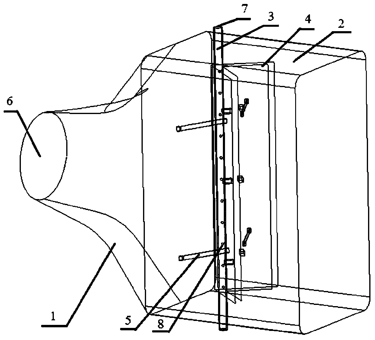
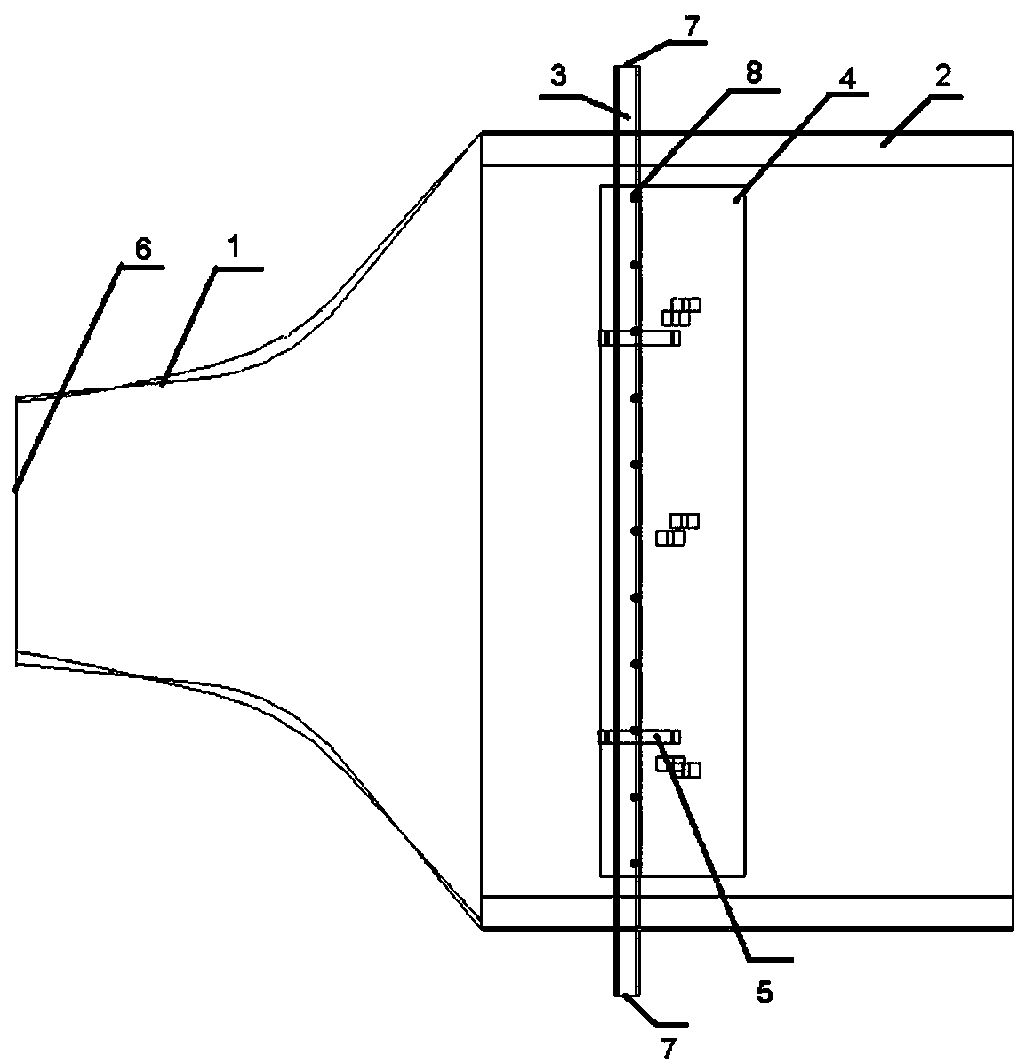
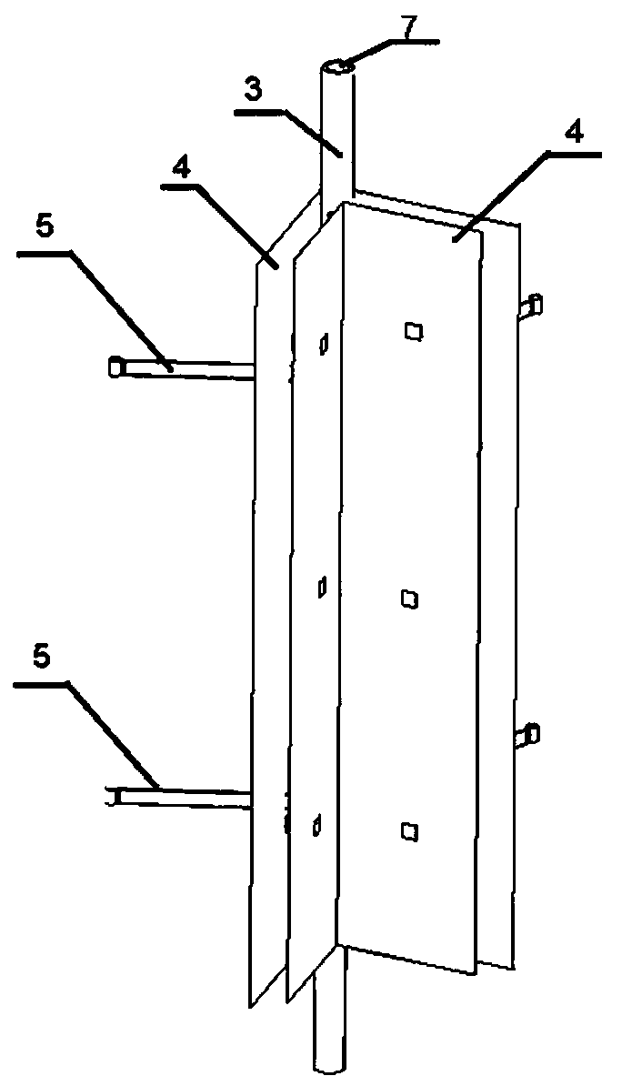
[0029] Such as Figure 1~2 As shown, the low-infrared radiation signal exhaust nozzle of the present invention is composed of a circular-to-rectangular transition section 1, a rectangular exhaust section 2, a cold air duct 3, a radiation shielding plate 4, and a radiation shielding plate pull rod 5, wherein the circular-to-rectangular transition section 1 is connected to the rectangular exhaust section 2. Inside the rectangular exhaust section 2, the cold air duct 3 vertically passes thr...


PUM


Abstract

The invention discloses a low-infrared radiation signal exhausting spray pipe which comprises a circle-rectangular transition section and a rectangular exhausting section. Cool air guide pipes are vertically connected with the upper end face and the lower end face of the rectangular exhausting section. Radiation baffle plates are connected to the front end face and the rear end face of the rectangular exhausting section correspondingly. Each radiation baffle plate is of a hollow structure. The radiation baffle plates on the two sides are of a V-shaped structure in the opening state. A small cool air guide pipe hole is formed in each cool air guide pipe. The hole forming direction is in a hollow interlayer of each radiation baffle plate. The invention further discloses an infrared restraining method of the pipe. On one hand, the V-shaped structure formed by the radiation baffle plates can shield infrared radiation radiated out by an upstream high-temperature part on the spray pipe; on the other hand, cool air in the cool air guide pipes enters the hollow interlayer of each radiation baffle plate, the surface temperature of the radiation baffle plates can be lowered, and therefore infrared radiation signals of the exhausting spray pipe are reduced greatly.

Description

technical field [0001] The invention belongs to the technical field of engine exhaust system design and infrared suppression, in particular to an infrared suppression device for an engine exhaust nozzle and an infrared suppression method thereof. Background technique [0002] In modern warfare, military helicopters are playing an increasingly important role in local combat areas, especially those with harsh geographical conditions. Many countries in the world have developed and strengthened helicopters as an important component of air power. . With the application of infrared detection and tracking technology, a large number of infrared guided weapons have appeared, which has caused a great threat to the survivability of helicopters with thermal power devices in a war environment. Engine exhaust nozzles must have the ability to reduce their infrared radiation, so as to Improve the helicopter's infrared countermeasures. [0003] At home and abroad, a lot of research work ha...

Claims


Application Information

Patent Timeline
Patent Type & Authority Patents(China)
IPC IPC(8): F02K1/38F02K1/78
CPCF02K1/38F02K1/78F05D2220/329F05D2240/15F05D2260/232
Inventor 单勇张靖周谭晓茗吕元伟
Owner NANJING UNIV OF AERONAUTICS & ASTRONAUTICS
Why Eureka
Try Eureka