
Impingement cooling structure based on array annular protruding target plate

A ring-shaped protrusion and cooling structure technology, which is applied in the direction of machines/engines, mechanical equipment, engine components, etc., can solve the problems of dimple structure disturbing wall surface protrusion structure, singleness, etc.

Pending Publication Date: 2021-09-10
NORTHWESTERN POLYTECHNICAL UNIV
View PDF11 Cites 0 Cited by
  • Summary
  • Abstract
  • Description
  • Claims
  • Application Information

AI Technical Summary

Problems solved by technology

Therefore, the present invention solves the problems in the prior art that the pit structure disturbs the wall surface and the convex structure is single, resulting in greater pressure loss and the like.

Method used


Image

  • Impingement cooling structure based on array annular protruding target plate
  • Impingement cooling structure based on array annular protruding target plate
  • Impingement cooling structure based on array annular protruding target plate

Examples


Embodiment

[0043] This implementation is an impingement cooling structure based on an array of annular convex target plates, including a cold air chamber, impact holes, impact target plates, annular protrusions, and air film holes.

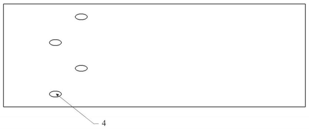
[0044] see figure 1 , the annular protruding structure 2 is located on the impact target plate, the spacing in the span direction is 24 mm, and the spacing in the flow direction is 30 mm. see figure 2 , The gas film hole is located on the side of the impact target plate without the impact hole, the diameter is 2.8mm, the distance between the flow direction and the span direction is 12mm, and the angle between the axis of the gas film hole and the impact target surface is 30°. see image 3 , the diameter of the impact hole is 3mm, the flow direction and the span direction spacing are consistent with the annular protrusion structure, the distance between the first row of impact holes and the center of the nearest air film hole is 28mm, and there is no annu...


PUM


Abstract

The invention relates to an impingement cooling structure based on an array annular protrusion target plate, and belongs to the field of engine turbines. The impingement cooling structure comprises an air inlet cavity, an impingement plate, the impingement target plate, array annular protrusions and a plurality of air film holes, wherein the array annular protrusions and the air film holes are arranged on the impingement target plate. The annular protrusions are located between adjacent impingement holes in the flow direction, and the spanwise distance and the flow direction distance of the array annular protrusions are consistent with those of the impingement holes. The air film holes are located in the downstream positions of the array annular protrusions on the impingement target plate in the flow direction. Cooling air is perpendicularly injected to the impingement target plate through the impingement holes, passes through the annular protrusions after being turned over by 90 degrees on the impingement target plate, flows to the downstream air film holes and flows out of the air film holes for external cooling. The heat exchange area is increased through the array annular protrusions, and therefore the purposes of increasing the heat exchange amount and enhancing the heat exchange effect are achieved. The annular protrusions can conduct secondary disturbance on fluid in the flow direction, and therefore disturbance is enhanced, and heat exchange is enhanced.

Description

technical field [0001] The invention belongs to the field of engine turbines, and in particular relates to an impingement cooling structure based on arrayed annular raised target plates. Background technique [0002] With the continuous development of aero-engine technology, the inlet temperature of the turbine has reached about 2000K, which has far exceeded the melting point of the materials used to manufacture high-temperature components. Necessary cooling of turbine blades, reducing their overall temperature level and local temperature difference, and ensuring no serious deformation or ablation within the required working range are of great significance to their long life and safe operation. Modern aero-engine turbine blades achieve the purpose of cooling the blades through reasonable coordination of internal cooling and external cooling. Among them, impingement cooling is the convective heat transfer form with the strongest heat transfer effect in internal cooling. [...

Claims


Application Information

Patent Timeline
Patent Type & Authority Applications(China)
IPC IPC(8): F01D25/12
CPCF01D25/12
Inventor 刘存良师晴晴李洁博张丽刘海涌
Owner NORTHWESTERN POLYTECHNICAL UNIV
Learn More