Torque converter

A technology of torque converter and clutch, applied in the field of power and transmission, can solve problems such as restricting the use of torque converter, and achieve the effect of improving load response capability and simple structure

Inactive Publication Date: 2017-05-17
SHANGLING CO LTD
View PDF5 Cites 0 Cited by
  • Summary
  • Abstract
  • Description
  • Claims
  • Application Information

AI Technical Summary

Problems solved by technology

[0002] Torque converters are widely used. However, traditional torque converter guide wheels are connected in the same direction as the turbine shaft, and the pump wheel is fixedly connected to the casing. This structure limits the use of torque converters.

Method used


Image

  • Torque converter
  • Torque converter
  • Torque converter

Examples


Embodiment 1

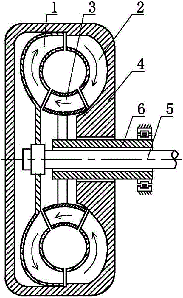
[0030] A torque converter, such as figure 1 As shown, it includes a pump wheel 1, a turbine 2, a guide wheel 3, and a housing 4. The pump wheel 1, the turbine 2 and the guide wheel 3 are arranged in the housing 4, and the pump wheel 1, The guide wheel 3 and the turbine 2 are arranged in series, the turbine 2 and the housing 4 are fixedly connected or integrally arranged, a shaft hole is provided on the housing 4, and a power is provided in the shaft hole. Input shaft 5. The power input shaft 5 is fixedly connected or integrated with the pump wheel 1, and a structural member 6 is provided between the shaft hole and the power input shaft 5; The guide wheel 3 is fixedly connected or integrated, and the structural member 6 is non-rotating or controlled.

Embodiment 2

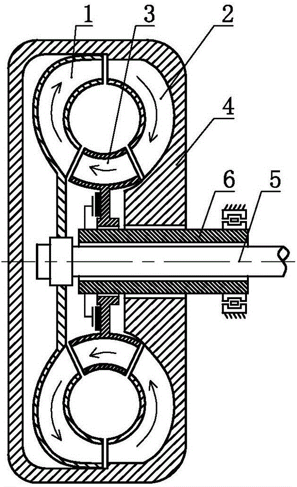
[0032] A torque converter, such as figure 2 As shown, it includes a pump wheel 1, a turbine 2, a guide wheel 3, and a housing 4. The pump wheel 1, the turbine 2 and the guide wheel 3 are arranged in the housing 4, and the pump wheel 1, The guide wheel 3 and the turbine 2 are arranged in series, the turbine 2 and the housing 4 are fixedly connected or integrally arranged, a shaft hole is provided on the housing 4, and a power is provided in the shaft hole. Input shaft 5. The power input shaft 5 is fixedly connected or integrated with the pump wheel 1, and a structural member 6 is arranged between the shaft hole and the power input shaft 5, and the structural member 6 passes through a clutch It is arranged in cooperation with the guide wheel 3, and the structural member 6 is arranged non-rotating or controlled.

[0033] As a transformable implementation, the second embodiment of the present invention can also selectively choose to make the structure 6 cooperate with the guide whee...

Embodiment 3

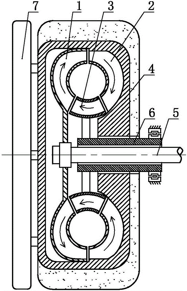
[0035] A torque converter, such as image 3 As shown, it includes a pump wheel 1, a turbine 2, a guide wheel 3, and a housing 4. The pump wheel 1, the turbine 2 and the guide wheel 3 are arranged in the housing 4, and the pump wheel 1, The guide wheel 3 and the turbine 2 are arranged in series, the turbine 2 and the housing 4 are fixedly connected or integrally arranged, a shaft hole is provided on the housing 4, and a power is provided in the shaft hole. Input shaft 5. The power input shaft 5 is fixedly connected or integrated with the pump wheel 1, and a structural member 6 is provided between the shaft hole and the power input shaft 5; the structural member 6 is The guide wheel 3 is fixedly connected or integrated, the structural member 6 is non-rotating or controlled, the housing 4 is weighted, and an inertia body 7 is provided on the housing 4.

[0036] As a transformable implementation, the third embodiment of the present invention can also selectively choose to increase th...


PUM


Abstract

The invention discloses a torque converter which comprises a pump wheel, a worm wheel, a guide wheel and a shell. The pump wheel, the worm wheel and the guide wheel are arranged in the shell, the pump wheel, the guide wheel and the worm wheel are connected in series, the worm wheel and the shell are fixedly connected or integrally arranged, a shaft hole is formed in the shell, a power input shaft is arranged in the shaft hole, the power input shaft and the pump wheel are fixedly connected or integrally arranged, and a structure piece is arranged between the shaft hole and the power input shaft; and the structure piece and the guide wheel are fixedly connected or integrally arranged, and the structure piece is arranged in a non-rotatable manner or arranged in a controlled manner. The torque converter is simple in structure, and the load response capacity of a power system using the torque converter can be effectively improved.

Description

Technical field [0001] The invention relates to the field of power and transmission, in particular to a torque converter. Background technique [0002] The torque converter is widely used. However, the guide wheel connection of the traditional torque converter is in the same direction as the turbine shaft, and the pump wheel is fixedly connected to the casing. This structure limits the use of the torque converter. Therefore, a new type of torque converter needs to be invented. Summary of the invention [0003] In order to solve the above problems, the technical solution proposed by the present invention is as follows: [0004] Solution 1: A torque converter, including a pump wheel, a turbine, a guide wheel, and a housing, the pump wheel, the turbine, and the guide wheel are arranged in the housing, the pump wheel and the guide wheel Is arranged in series with the turbine, the turbine is fixedly connected to the housing or integrally arranged, a shaft hole is provided on the housin...

Claims


Application Information

Patent Timeline
Patent Type & Authority Applications(China)
IPC IPC(8): F16H41/04F16H41/24
CPCF16H41/04F16H41/24
Inventor 靳北彪
Owner SHANGLING CO LTD
Why Eureka
Try Eureka