Double-surface three-dimensional reconstructing method, device and system for transparent object

A 3D reconstruction and target technology, applied in the field of computer vision, can solve problems such as large amount of calculation and low efficiency

Inactive Publication Date: 2017-05-17
CHANGCHUN UNIV OF SCI & TECH
View PDF1 Cites 14 Cited by
  • Summary
  • Abstract
  • Description
  • Claims
  • Application Information

AI Technical Summary

Problems solved by technology

[0005] The present invention provides a double-surface three-dimensional reconstruction method, device and system of a transparent object, which are used to solve the technical problems of relatively large amount of calculation and low efficiency in performing three-dimensional reconstruction in the prior art

Method used


Image

  • Double-surface three-dimensional reconstructing method, device and system for transparent object
  • Double-surface three-dimensional reconstructing method, device and system for transparent object
  • Double-surface three-dimensional reconstructing method, device and system for transparent object

Examples


Embodiment 1

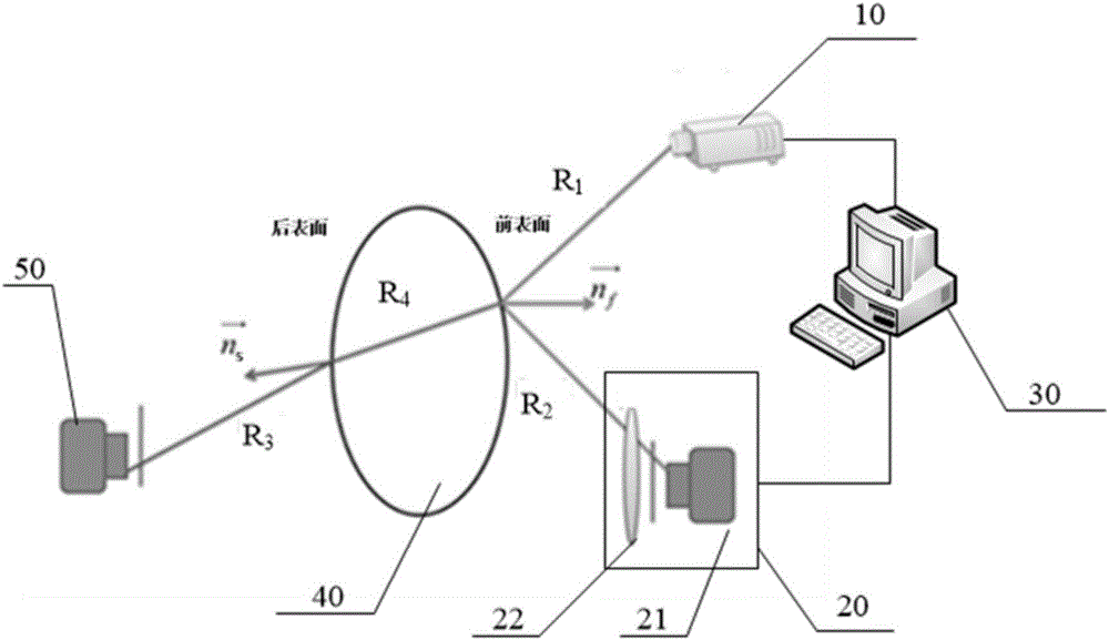
[0085] figure 1 Schematic diagram of the structure of the double-surface three-dimensional reconstruction system for the transparent target provided by the embodiment of the present invention, as shown in figure 1 As shown, it includes: a light emitting end 10 , a first camera end 20 , a dual-surface three-dimensional reconstruction device 30 , a transparent target 40 and a second camera end 50 .

[0086] The system provided in this embodiment is used for three-dimensional reconstruction of the front surface and the back surface of the transparent object 40 . Wherein, the front surface and the rear surface are set opposite to each other.

[0087] Specifically, the light emitting end 10 adopts natural light as the incident light R in the form of a surface light source. 1 illuminating the front surface of the transparent target, on the one hand, the incident light R 1 A part of it is reflected by the front surface, denoted as reflected light R 2 , the other part is reflected...

Embodiment 2

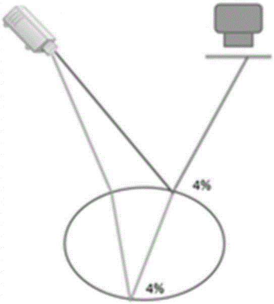
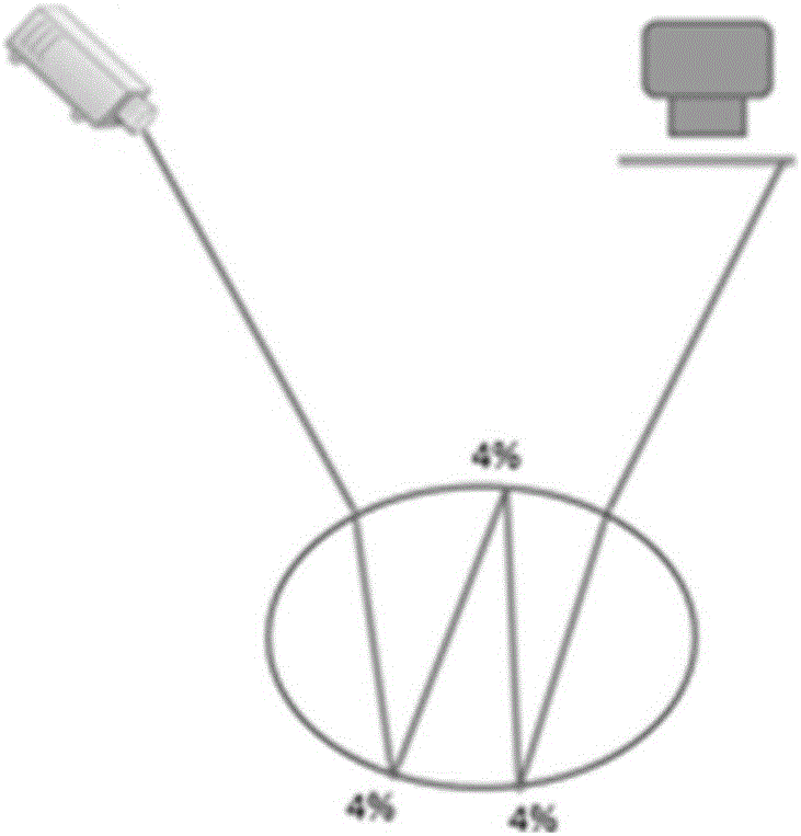
[0097] In order to improve the reconstruction efficiency, in this embodiment and the previous embodiment, the light-emitting end 10 adopts a surface light source to output the incident light R 1 , to avoid the scanning process when using a point light source. Specifically, there are multiple pixel points on the light source plane of the light emitting end 10, which are called second pixel points to distinguish them from the first pixel points of the camera in the first camera end 20. The second pixel points on the light source plane emit The incident light R 1 , after being reflected by the front surface, the first camera terminal 20 receives the reflected light R 2 .

[0098] However, while the surface light source improves the reconstruction efficiency on the one hand, it also causes the reflected light R on the front surface 2 The problem of coincidence with the reflected light of the rear surface, so that the first camera end 20 not only receives the reflected light R o...

Embodiment 3

[0133] In order to clearly illustrate the aforementioned embodiment, the mentioned dual-surface three-dimensional reconstruction device 30, Figure 9 is a schematic structural diagram of a dual-surface three-dimensional reconstruction device 30, such as Figure 9 As shown, the dual-surface three-dimensional reconstruction device 30 includes: a light intensity calculation module 31 , a front surface reconstruction module 32 , and a rear surface reconstruction module 33 .

[0134] The light intensity calculation module 31 is used to, in the triangulation optical path, according to the relationship between the reflected light intensity of the front surface and the polarization angle, and the relationship between the reflected light intensity of the rear surface and the polarization angle, from the From the light intensity of each piece of reflected light at each polarization angle measured by the first camera end, determine the light intensity of each piece of reflected light on ...


PUM


Abstract

An embodiment of the invention provides a double-surface three-dimensional reconstructing method, device and system for a transparent object. Natural light is adopted as incident light at a light emitting end for radiating the transparent object. The incident light is reflected by a front surface and a rear surface and reflective light is obtained. The reflective light is received by a first camera end and transmission light of the transparent object is received by a second camera end. When three-dimensional reconstruction of the front surface is performed, a polarization analysis method is utilized. The direction vectors of the incident light and the reflective light are obtained based on the polarization degree of the reflective light. On this basis, the space location of the incident light and the space location of the reflective light are determined by utilizing a trigonometric survey method. Since the trigonometric survey method and the polarization analysis method are adopted at the same time for obtaining reconstruction information, the space location of the incident light and the space location of the reflective light are determined. Construction is performed according to the cross point of the two space locations and the calculation steps of three-dimensional reconstruction is simplified.

Description

technical field [0001] The invention relates to computer vision technology, in particular to a double-surface three-dimensional reconstruction method, device and system for a transparent target. Background technique [0002] Three-dimensional reconstruction refers to the establishment of a mathematical model suitable for computer representation and processing of three-dimensional objects, which is the basis for processing, operating and analyzing its properties in a computer environment, and is also a key technology for establishing a virtual reality that expresses the objective world in a computer . [0003] In computer vision, the 3D reconstruction technology of transparent objects has always been a hot topic in the field of machine vision. It has been continuously developed in recent years, and a variety of 3D reconstruction methods have been proposed, such as reconstruction based on deformation method, optical path triangulation, polarization analysis and other methods....

Claims


Application Information

Patent Timeline
Patent Type & Authority Applications(China)
IPC IPC(8): G06T17/30
CPCG06T17/30
Inventor 乔杨徐熙平潘越徐昕阳
Owner CHANGCHUN UNIV OF SCI & TECH
Why Eureka
Try Eureka