
coil holder

A coil support, basic block technology, applied in the direction of transformer/inductor coil/winding/connection, transformer, electrical components, etc., can solve the problems of complex process, high cost, high designer requirements, etc.

Active Publication Date: 2018-04-24
ZONECHARGE (SHENZHEN) WIRELESS POWER TECH CO LTD
View PDF7 Cites 0 Cited by
  • Summary
  • Abstract
  • Description
  • Claims
  • Application Information

AI Technical Summary

Problems solved by technology

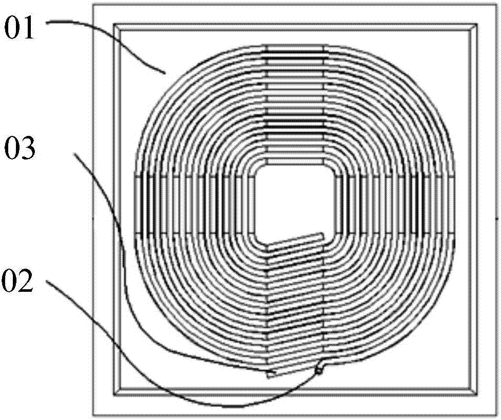
[0004] However, the process of this kind of bracket 01 is complicated, the requirements for designers are high, and the cost is high. The time for coil proofing is usually about half a month. At the same time, one bracket 01 can only correspond to one coil winding method and corresponds to A fixed inductance, if the design is wrong, the entire bracket 01 will be scrapped, especially not suitable for the experimental research and development stage

Method used


Image

  • coil holder
  • coil holder
  • coil holder

Examples


Embodiment Construction

[0042] The following will clearly and completely describe the technical solutions in the embodiments of the present invention with reference to the accompanying drawings in the embodiments of the present invention. Obviously, the described embodiments are only some, not all, embodiments of the present invention. Based on the embodiments of the present invention, all other embodiments obtained by persons of ordinary skill in the art without making creative efforts belong to the protection scope of the present invention.

[0043] The core of the present invention is to provide a coil support with high flexibility in use.

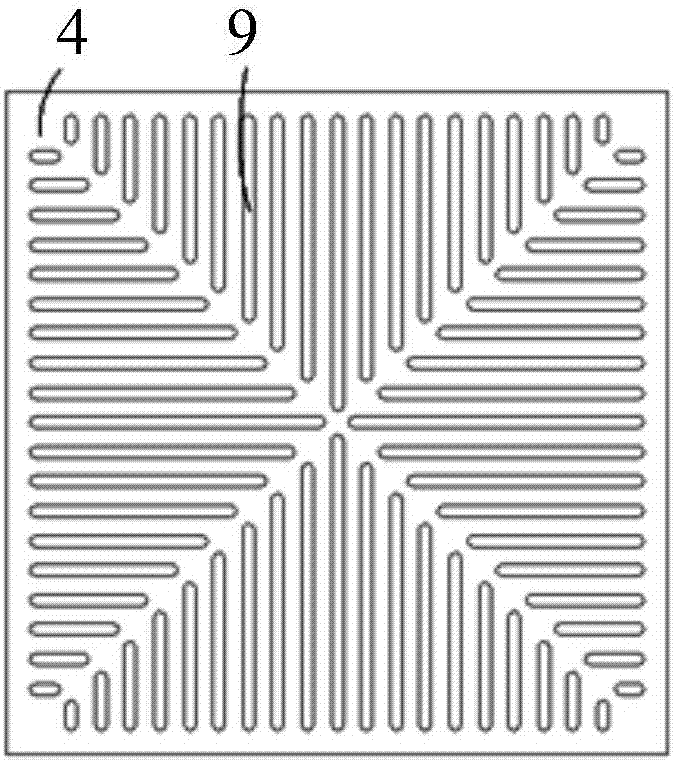
[0044] Please refer to Figure 3 to Figure 9 , image 3 A top view of the bottom plate in a specific embodiment of the coil support provided by the present invention; Figure 4 It is a structural schematic diagram of the bottom plate in a specific embodiment of the coil support provided by the present invention; Figure 5 A cross-sectional view of the botto...


PUM


Abstract

The invention discloses a coil support which comprises a bottom plate and a plurality of basic blocks, wherein the bottom plate comprises a plurality of mounting positions arranged along preset direction, the basic blocks are detachably arranged on the mounting positions, and the two adjacent basic blocks are matched to form a clamping groove for clamping litz wires. According to the actual size of the litz wires, the mounting positions of the basic blocks on the bottom plate are selected and spliced into suitable coil supports, the coil support is simple to operate and good in use flexibility, cost is saved, the coil support can be disassembled and reassembled in a short time, coil supports of various groove widths can be spliced as mounting modes of the coil supports are flexible at the experimental development phase, and a lot of experimental proofing time can be saved.

Description

technical field [0001] The invention relates to the technical field of radio power supply, in particular to a coil support. Background technique [0002] Wireless power supply is a new high-tech industry and can be applied to wireless charging of electric vehicles. The wireless charging system is mainly composed of a transmitting controller, a transmitting coil, a receiving coil, and a receiving controller. In the research and development stage, the most important and most frequently adjusted are the transmitting and receiving coils. The coil is a structure in which litz wire is wound flat with a certain diameter, its height is generally the diameter of the litz wire, and its width is generally the number of turns of the coil composed of the litz wire. Although the principle of the coil is simple, the winding test is not easy. The Litz wire is slightly deformed, and the inductance will change. After the coil is wound, the matching of the parameters of the coil and the syste...

Claims


Application Information

Patent Timeline
Patent Type & Authority Patents(China)
IPC IPC(8): H01F38/14H01F27/30H02J50/10
CPCH01F27/306H01F38/14H01F2038/143H02J7/025
Inventor 肖帅马邦华周仲兵
Owner ZONECHARGE (SHENZHEN) WIRELESS POWER TECH CO LTD
Learn More