Supercharge Your Innovation With Domain-Expert AI Agents!

Battery core shell assembling-into positioning device

A positioning device and cell technology, applied in non-aqueous electrolyte storage batteries, electrolyte storage battery manufacturing, sustainable manufacturing/processing, etc. Shell quality, damage reduction, and the effect of reducing failure rates

Pending Publication Date: 2017-05-17
WUXI LEAD INTELLIGENT EQUIP CO LTD
View PDF3 Cites 3 Cited by
  • Summary
  • Abstract
  • Description
  • Claims
  • Application Information

AI Technical Summary

Problems solved by technology

[0002] In the production process of lithium-ion batteries, after the ultrasonic welding of the tabs is completed, the bare cells packed in Mylar are put into the steel shell or aluminum shell for welding. The smaller the gap between the cell and the shell, the better the battery produced will be. The safer it is, but if the gap between the battery core and the shell is too small, it will make it difficult for the battery core to enter the shell
In the prior art, one is completed in the form of manual assistance. When the battery is manually operated, it is inevitable to pass through manual contact, and it is easy to leave pollutants such as sweat on the battery, which is easy to cause quality problems; the other is Automated mechanical equipment is used, but when entering the shell, the shell mouth is easy to scratch the Mylar, short-circuiting the battery cells, and the scrap rate is high
In the existing shelling machine, there is no guiding and positioning mechanism, and there is no shell opening mechanism, which leads to low accuracy of the shelling of the battery cells, and the battery cells are easily damaged

Method used


Image

  • Battery core shell assembling-into positioning device
  • Battery core shell assembling-into positioning device
  • Battery core shell assembling-into positioning device

Examples


Embodiment Construction

[0024] The present invention will be further described below in conjunction with specific drawings.

[0025] In the description of the following specific embodiments, with figure 1 The direction to the left in the middle is the front, figure 1 The direction to the right in the middle is the back, the direction perpendicular to the outside of the paper is left, and the direction vertical to the inside of the paper is right.

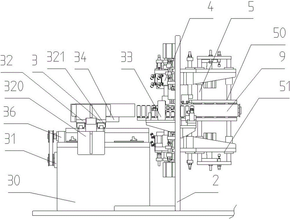
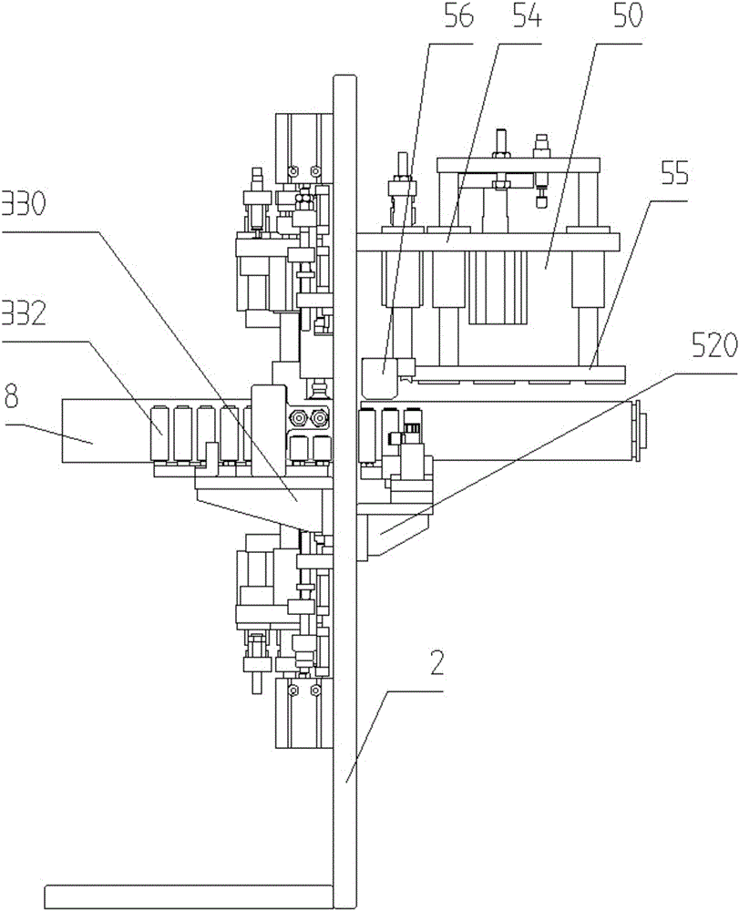
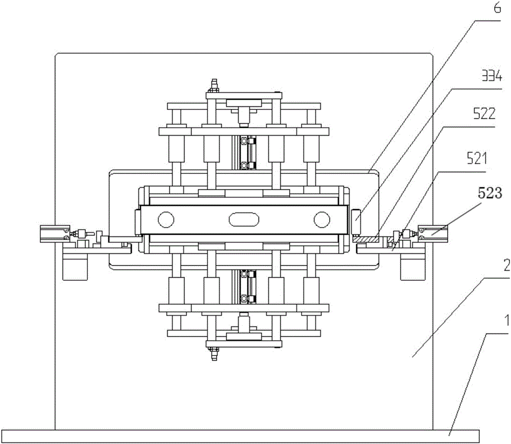
[0026] Such as Figure 1 to Figure 9 As shown, the electric core positioning device of the present invention is used to send the electric core 9 into the shell 8, including the bottom plate 1, the vertical plate 2, the shell driving positioning mechanism 3, the shell opening mechanism 4 and the electric core Shell entry positioning mechanism 5, the vertical plate 2 is vertically installed in the middle of the bottom plate 1, the vertical plate 2 is provided with a cell entry 6, the shell opening mechanism 4 is installed on the front side of the vertical ...


PUM


Abstract

The invention relates to a battery core shell assembling-into positioning device. The battery core shell assembling-into positioning device is characterized by comprising a vertical plate in which a battery core shell assembling-into inlet is formed, wherein a shell strutting mechanism and a shell assembling-into opening mechanism are arranged on the front side face of the vertical plate, and a battery core assembling-into positioning mechanism is arranged on the rear side face of the vertical plate; the shell strutting mechanism comprises first suction nozzles for adsorbing the left side and the right side of the shell, and the first suction nozzles are connected with a driving device for driving the first suction nozzles to move in the horizontal direction; the shell assembling-into opening mechanism comprises second suction nozzles for adsorbing the upper side and the lower side of the shell, and the second suction nozzles are connected with the power output end of a driving device for driving the second suction nozzles to move in the vertical direction; the battery core assembling-into positioning mechanism comprises a vertical guide roller and a horizontal guide roller, the vertical guide roller is connected with the power output end of a driving device for driving the vertical guide roller to move in the vertical direction, and the horizontal guide roller is connected with the power output end of a driving device for driving the horizontal guide roller to move in the horizontal direction. According to the device, the battery core shell assembling-into quality can be improved, and the damage of battery cores is reduced.

Description

technical field [0001] The invention relates to a positioning device for battery cells inserted into a case, and belongs to the technical field of lithium-ion battery manufacturing equipment. Background technique [0002] In the production process of lithium-ion batteries, after the ultrasonic welding of the tabs is completed, the bare cells packed in Mylar are put into the steel shell or aluminum shell for welding. The smaller the gap between the cell and the shell, the better the battery produced will be. The safer it is, but if the gap between the battery cell and the shell is too small, it will make it difficult for the battery core to enter the shell. In the prior art, one is completed in the form of manual assistance. When the battery is manually operated, it is inevitable to pass through manual contact, and it is easy to leave pollutants such as sweat on the battery, which is easy to cause quality problems; the other is It adopts automatic mechanical equipment, but w...

Claims


Application Information

Patent Timeline
IPC IPC(8): H01M10/058
CPCH01M10/058Y02E60/10Y02P70/50
Inventor 夏荣兵
Owner WUXI LEAD INTELLIGENT EQUIP CO LTD
Features
  • R&D
  • Intellectual Property
  • Life Sciences
  • Materials
  • Tech Scout
  • Unparalleled Data Quality
  • Higher Quality Content
  • 60% Fewer Hallucinations
Learn More