
Broadband high-isolation 2*2 microstrip antenna

A technology of microstrip antenna and high isolation, which is applied in the direction of antenna, antenna coupling, antenna unit combination with different polarization directions, etc. It can solve the problem of narrow working bandwidth of microstrip antenna, limitation of broadband wireless communication application, limitation of application of microstrip antenna, etc. problems, to achieve the effect of broadening the application market and improving the isolation

Inactive Publication Date: 2017-05-17
上海捷士太通讯技术有限公司
View PDF0 Cites 0 Cited by
  • Summary
  • Abstract
  • Description
  • Claims
  • Application Information

AI Technical Summary

Problems solved by technology

However, the shortcoming (<5%) of the narrow operating bandwidth of the microstrip antenna also greatly limits the application of the microstrip antenna.
In recent years, with the advent of the era of high-speed data communication, broadband wireless communication has developed rapidly. Broadband wireless communication requires a relatively wide operating bandwidth, and the shortcoming of the narrow operating bandwidth of the microstrip antenna limits its application in the rapidly developing field of broadband wireless communication.

Method used


Image

  • Broadband high-isolation 2*2 microstrip antenna
  • Broadband high-isolation 2*2 microstrip antenna
  • Broadband high-isolation 2*2 microstrip antenna

Examples


specific Embodiment approach

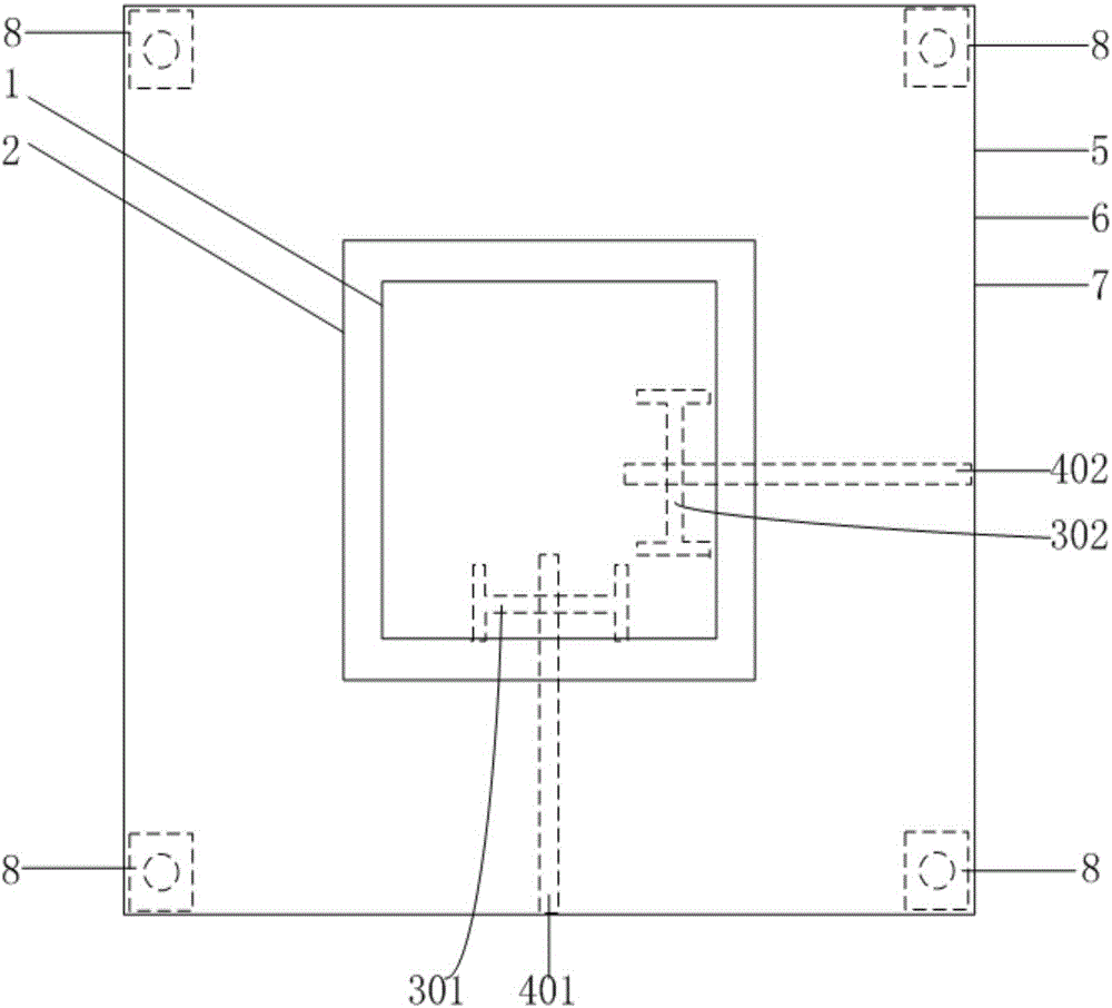
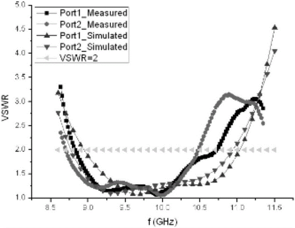
[0021] Figure 1-Figure 2 Show the specific implementation of the broadband high isolation 2x2 microstrip antenna of the present invention: a broadband high isolation 2x2 MIMO microstrip antenna, including the first radiation unit 1, the second radiation unit 2, the first H-shaped slot 301, the second H-shaped Slot 302 , first feed unit 401 , second feed unit 402 , first dielectric substrate 5 , second dielectric substrate 6 , third dielectric substrate 7 , air dielectric layer 9 , ground layer 10 and gasket 8 . The first radiation unit 1 is attached to the upper surface of the first dielectric substrate 5, the second radiation unit 2 is attached to the upper surface of the second substrate 6, and the space between the first dielectric substrate 5 and the second dielectric substrate 6 is air The dielectric layer 9 is supported by the gasket 8. The formation 10 is attached to the lower surface of the second dielectric substrate 6 and the upper surface of the third dielectric s...


PUM


Abstract

The present invention discloses a broadband high-isolation 2*2 microstrip antenna and belongs to the antenna technical field. The broadband high-isolation 2*2 microstrip antenna comprises a first radiating element, a second radiating element, a first H-shaped open slot, a second H-shaped open slot, a first feeding unit, a second feeding unit, a first dielectric substrate, a second dielectric substrate, a third dielectric substrate, an air dielectric layer, ground layers and spacers; the first radiating element is attached onto the upper surface of the first dielectric substrate; the second radiating element is attached onto the upper surface of the second substrate; the air dielectric layer is located between the first dielectric substrate and the second dielectric substrate and is supported by the spacers; the ground layers are attached onto the lower surface of the second dielectric substrate and the upper surface of the third dielectric substrate respectively; the two ground layers contact with each other; the first feeding unit and the second feeding unit are attached onto the lower surface of the third dielectric substrate; the first H-shaped open slot and the second H-shaped open slot are H-shaped open slots formed in the ground layers; the first H-shaped open slot and the second H-shaped open slot are perpendicular to each other in physical directions; and the first feeding unit and the second feeding unit are perpendicular to each other in physical directions.

Description

technical field [0001] The invention relates to the technical field of antennas, in particular to a broadband high-isolation 2x2 microstrip antenna. Background technique [0002] In recent years, with the rapid development of communication technology, wireless mobile communication has also been widely used. The antenna is an important part of the wireless mobile communication system, responsible for sending and receiving wireless signals. [0003] Among many types of antennas, microstrip antennas are favored by the market and widely used due to their small size, light weight, planar structure, easy integration with IC devices, easy mass production, and low cost. However, the shortcoming of the narrow working bandwidth (<5%) of the microstrip antenna also greatly limits the application of the microstrip antenna. In recent years, with the advent of the era of high-speed data communication, broadband wireless communication has developed rapidly. Broadband wireless communic...

Claims


Application Information

Patent Timeline
IPC IPC(8): H01Q1/38H01Q1/52H01Q13/08H01Q21/24
CPCH01Q1/38H01Q1/52H01Q13/08H01Q13/085H01Q21/24
Inventor 鲁勇
Owner 上海捷士太通讯技术有限公司
Learn More