Installation structure of cooling water tank and electrical control components of electromagnetic heating device
An electromagnetic heating device and electrical control technology, applied in the direction of induction heating, coil device, fluid heater, etc., can solve the problems of electrical control components that cannot be tightly fitted, water seepage danger, warping and deformation, etc., so as to avoid water seepage or The effect of anti-seepage is required
- Summary
- Abstract
- Description
- Claims
- Application Information
AI Technical Summary
Problems solved by technology
Method used
Image

Examples
Embodiment 1
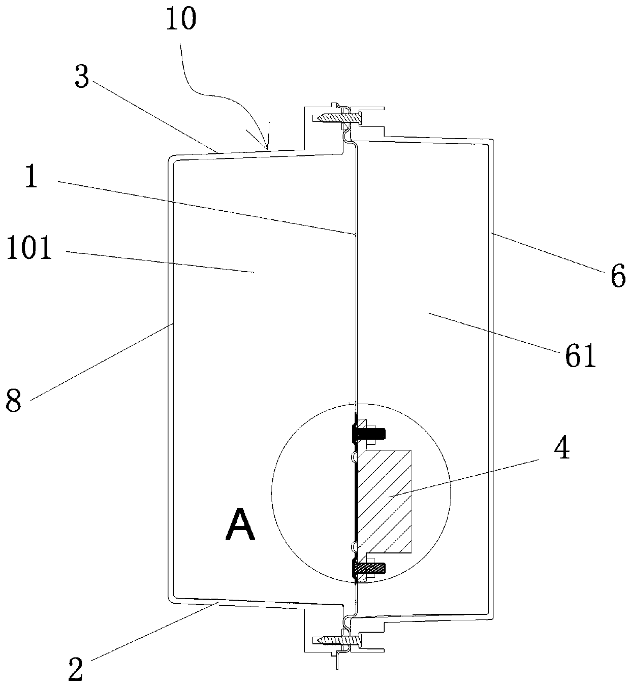
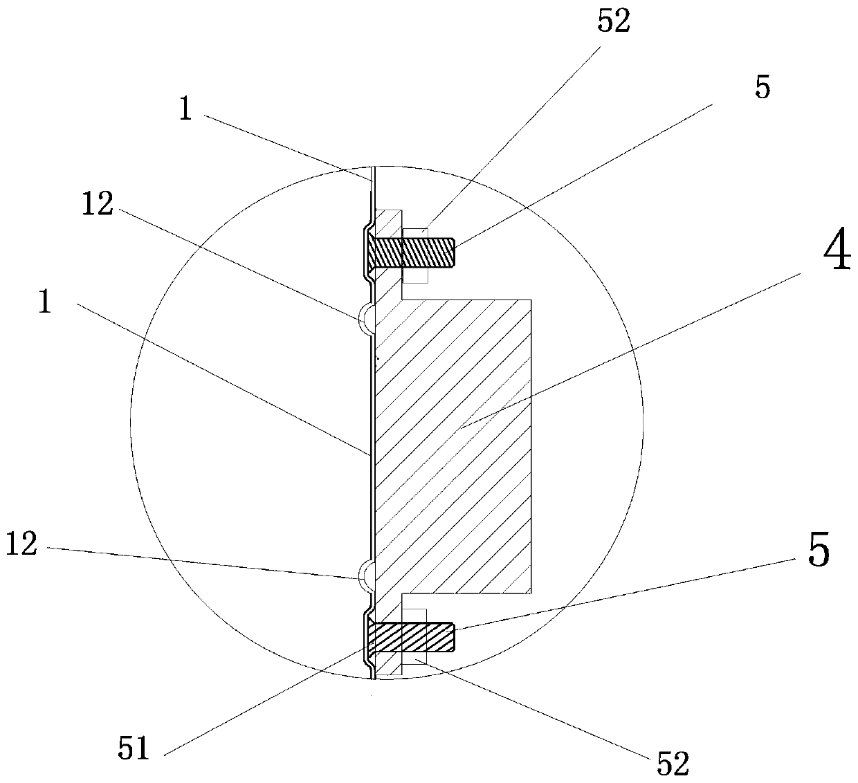
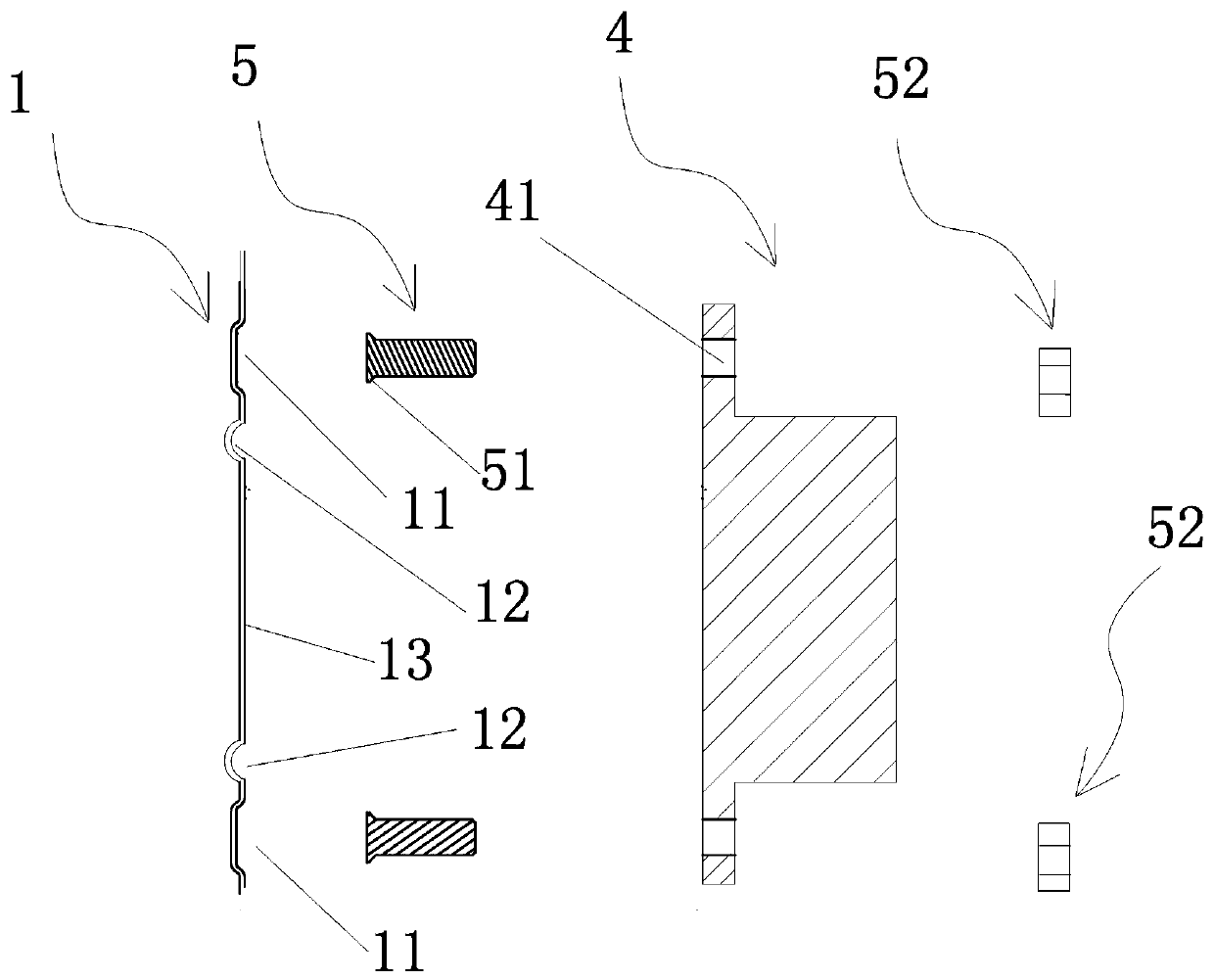
[0028] figure 1 , figure 2 , image 3 , Figure 4 As shown, the cooling water tank and the electrical control element installation structure of the electromagnetic heating device include a cooling water tank 10 and an electrical control element 4. The cooling water tank is provided with six surfaces, which are respectively the first box wall 1, the second box wall 8, and the third box wall. The tank wall (not shown in the figure), the fourth tank wall (not shown in the figure), the bottom wall 2 and the top plate 3 form a water tank cavity 101 after being surrounded by them. Among them, the first tank wall 1 of the cooling water tank is a stainless steel metal wall, and the tank walls adjacent to the metal wall 1 (including the bottom wall 2, the top plate 3, the second tank wall 8, the third tank wall, and the fourth tank wall) It is a non-metallic wall, and an outer cover 6 is fixedly connected to the outside of the metal wall 1 of the cooling water tank, and a chamber 6...
Embodiment 2
[0034] The main difference between Embodiment 1 and Embodiment 2 is that the "fireproof line" of the deformation of the barrier metal wall in Embodiment 1 is an annular annular groove, while the corresponding structure of the deformation of the barrier metal wall in Embodiment 2 is changed to an annular ring protrusion. order 14, such as Figure 9 As shown, the annular step 14 extends along the edge region of the electrical control element and connects end to end. The metal wall area 13 surrounded by the annular protrusion 14 is raised relative to the metal wall area 15 on the periphery of the annular protrusion, and the metal wall area 13 surrounded by the annular protrusion is closely attached to the electrical control element 4. The annular protrusion of the metal bolt 5 The metal wall at the periphery of the step is welded and fixed, so the connecting point between the nut 51 and the metal wall is located at the periphery of the annular protruding step; in addition, the me...
PUM
 Abstract
Description
Claims
Application Information
 - R&D
- Intellectual Property
- Life Sciences
- Materials
- Tech Scout
- Unparalleled Data Quality
- Higher Quality Content
- 60% Fewer Hallucinations
Browse by: Latest US Patents, China's latest patents, Technical Efficacy Thesaurus, Application Domain, Technology Topic, Popular Technical Reports.
© 2025 PatSnap. All rights reserved.Legal|Privacy policy|Modern Slavery Act Transparency Statement|Sitemap|About US| Contact US: help@patsnap.com