Flexible bone reamer

A drill, flexible technology, used in medical science, surgery, etc.

Active Publication Date: 2017-05-17
BIOMET MFG CORP
View PDF14 Cites 3 Cited by
  • Summary
  • Abstract
  • Description
  • Claims
  • Application Information

AI Technical Summary

Problems solved by technology

[0006] While known surgical procedures for drilling bones including the shoulder joint have prove...

Method used


Image

  • Flexible bone reamer
  • Flexible bone reamer
  • Flexible bone reamer

Examples


Embodiment Construction

[0033] Exemplary embodiments will now be described more fully with reference to the accompanying drawings.

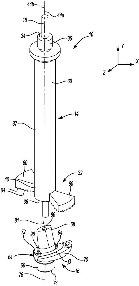
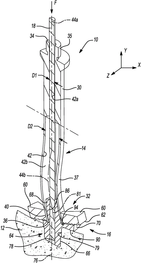
[0034] First refer to figure 1 with figure 2 , a drilling system constructed in accordance with the principles of the present invention is shown and indicated at 10 . Such as figure 2 As shown in , according to one exemplary use, the drilling system 10 may be used to prepare the glenoid socket 12 of the shoulder joint during shoulder arthroplasty. However, it will also be understood that the present teachings are applicable to preparing a variety of bones and joints during surgery.

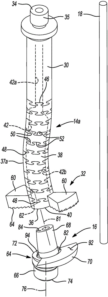
[0035] The drilling system 10 may generally include a drill 14 , a guide 16 and a guide wire 18 . Before addressing specific components of the drilling system 10, a brief discussion of an exemplary environment of use is warranted. The shoulder joint is generally formed between the humerus (not shown) and the glenoid portion 12 of the scapula. Specifically, a portion of the humerus (...


PUM


Abstract

A bone reamer (14) includes a shaft (30) and a cutting element (32). The shaft includes a proximal end (34), a distal end (36), and a flexible portion (37) disposed between the proximal and distal ends. The cutting element is carried by the shaft and includes a cutting surface (62) facing the distal end of the shaft such that the distal end of the shaft is offset from the cutting surface. The cutting element may have arms (60) and a propeller-shaped profile. The shaft defines a cannula (42). A guide (16) for the bone reamer has a boss (66) along a first axis (76), a hub (68) along a second axis (81) forming an angle [alpha] with the first axis, and a flange (70) substantially perpendicular to the second axis. The reamer can be used for reaming the glenoid.

Description

[0001] claim priority [0002] This application claims the benefit of, thereby claiming priority from, US Patent Application No. 14 / 460,079, filed August 14, 2014, and is hereby incorporated by reference in its entirety. technical field [0003] The present invention generally relates to an apparatus and method for drilling bone, and more particularly to a bone drill having a flexible shaft portion. Background technique [0004] This section provides background information related to the present disclosure and is not necessarily prior art. [0005] Surgical procedures used to repair or reconstruct a joint may require the secure fastening of a surgical implant to bone. For example, a procedure such as reverse shoulder arthroplasty to reconstruct the shoulder joint may require the fixation of a glenoid implant to the scapula in order to reconstruct or replicate the glenoid on the scapula. These procedures may involve securing bone grafts to the glenoid socket and / or drilling...

Claims


Application Information

Patent Timeline
IPC IPC(8): A61B17/16
CPCA61B17/1615A61B17/1631A61B17/1684A61B2017/1602A61B17/1778
Inventor M·F·科瓦克斯T·M·瓦纳斯
Owner BIOMET MFG CORP
Why Eureka
Try Eureka