
A water sealing device for tail gas purification in chemical storage tanks

A technology of exhaust gas purification and water sealing device, applied in chemical instruments and methods, separation methods, dispersed particle separation, etc., can solve the problems of hindering the suction of storage tanks, negative pressure of storage tanks, low safety, etc., and avoid sludge Blocking and ensuring unobstructed effect

Active Publication Date: 2019-06-18
BAOWU CHARCOAL MATERIAL TECH CO LTD
View PDF4 Cites 0 Cited by
  • Summary
  • Abstract
  • Description
  • Claims
  • Application Information

AI Technical Summary

Problems solved by technology

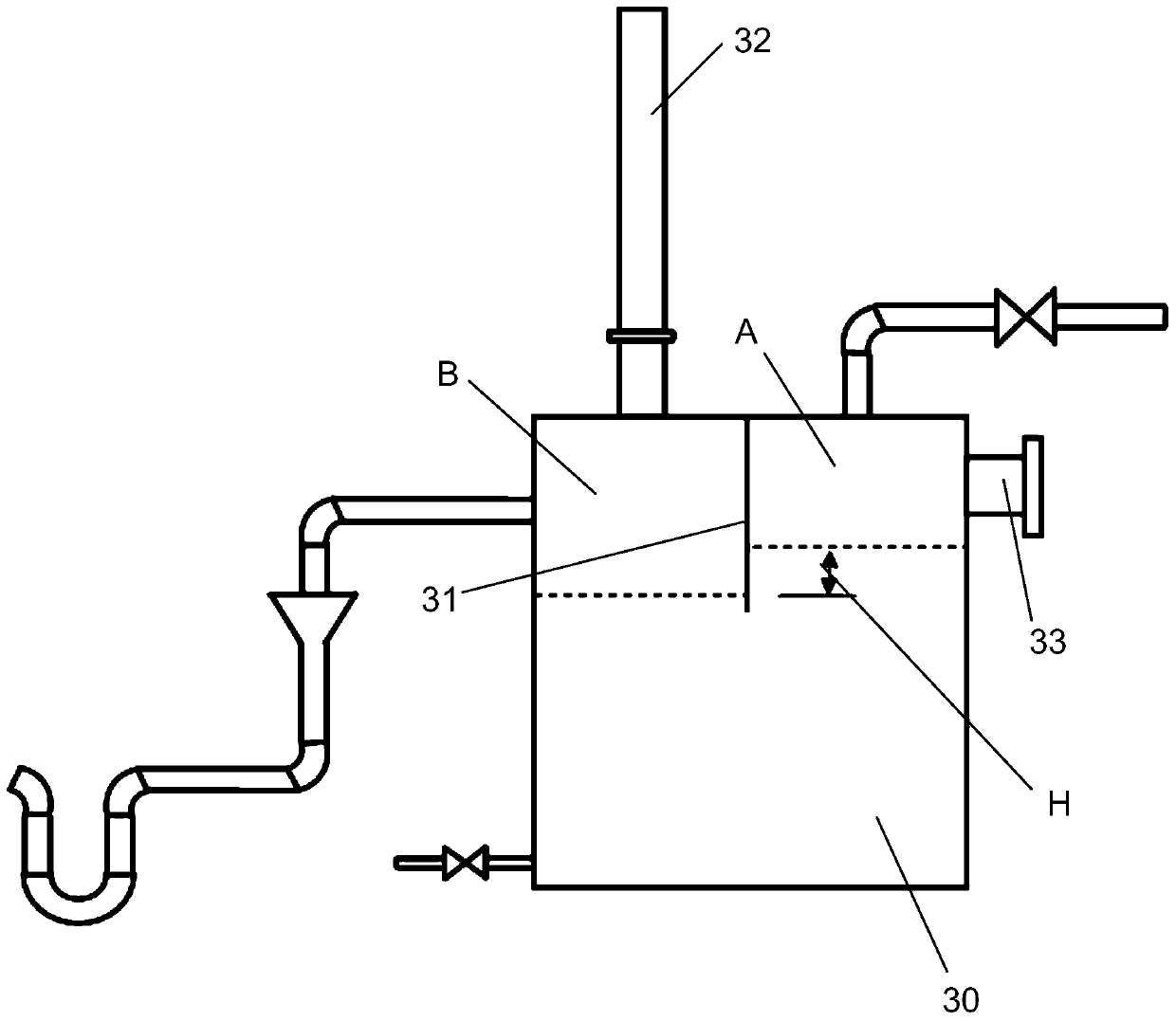
[0004] To sum up, the method of this utility model is simple in structure and low in cost, but the safety is not high in practical application. This is because, when the suction strength of the storage tank is high, the sewage will It will be sucked into the storage tank, and this defect will seriously affect the quality of chemical products in which the water content is strictly controlled in the storage tank; in addition, if the storage tank absorbs air, the sewage will remain in the vertical connection pipe between the water sealing device and the storage tank, Since the vertical connecting pipes are usually relatively slender, the sewage flowing into the connecting pipes will form a water seal with a height much higher than H, which will seriously hinder the storage tank from sucking air, causing severe negative pressure in the storage tank. When the water seal height of the connecting pipeline reaches 10cm, the tank wall of the storage tank will be deformed due to the high pressure. , it is not uncommon for storage tanks to be “sucked up” due to negative pressure

Method used


Image

  • A water sealing device for tail gas purification in chemical storage tanks
  • A water sealing device for tail gas purification in chemical storage tanks

Examples


Embodiment Construction

[0024] The technical solutions of the present invention will be further described below in conjunction with the accompanying drawings and embodiments.

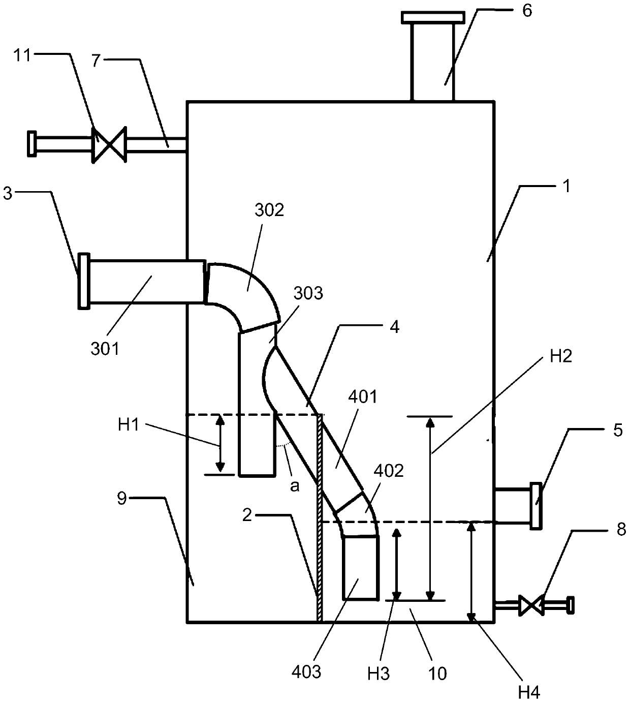
[0025] Please combine figure 2 As shown, a kind of water sealing device used for purification of tail gas in chemical storage tanks of the present invention is the same as the prior art in that it also includes a water tank 1 and an exhaust pipe 6 connected to the top of the water tank, which will not be repeated here. Different from the prior art, it also includes a baffle 2, an intake pipe 3, a water storage pipe 4, a water supply pipe 7, an overflow pipe 5 and a sewage pipe 8, and the baffle 2 is erected at the inner bottom of the water tank 1 to The interior of the water tank is divided into a water purification chamber 9 and a sewage chamber 10. The air intake pipe 3 includes an air intake horizontal pipe 301, an air intake elbow 302 and an air intake vertical pipe 303. One end of the air intake horizontal pipe 301 is in...


PUM


Abstract

The invention discloses a water seal device used for purifying tail gas in chemical engineering storage tanks. The water seal device comprises a water tank, an exhaust pipe connected with the top of the water tank, an separating plate, a gas inlet pipe, a water storage pipe, a water supplying pipe, an overflow pipe, and a discharge pipe; the separating plate is vertically arranged on the bottom in the water tank so as to separate the water tank into a clear water chamber and a sewage chamber; one end of the gas inlet is inserted into one side of the clear chamber of the water tank, and the other end is arranged in the water tank with an opening arranged to be downward above the clear water chamber; one end of the water storage pipe is communicated with one side of the gas inlet pipe in the water tank, and the other end is arranged to be above the sewage chamber after passing through the separating plate; the water supplying pile is arranged on one side of the clear water chamber of the water tank above the gas inlet pile; the sewage pipe is arranged on the bottom of one side of the sewage chamber in the water tank; the overflow pipe is arranged on one side of the sewage chamber in the water tank above the discharge pile. No other operation is needed after adjusting of water supplying speed; structure is simple; cost is low; operation is convenient; maintenance cost is low; and the water seal device is safe and reliable.

Description

technical field [0001] The invention relates to a water sealing device, more specifically, to a water sealing device used for purifying tail gas in a chemical storage tank. Background technique [0002] In the production process of coal chemical products, it is necessary to use storage tanks to store chemical intermediates or end products such as acid and alkali, waste liquid, etc., and a large amount of toxic and harmful waste gas produced by chemical products that can cause cancer often accumulates on the top of these storage tanks . There are four existing methods for treating waste gas in storage tanks: installing breathing valves and release pipes, setting up exhaust gas cleaning towers, setting up waste gas incineration devices, and setting up water seal devices. Occasions, treatment costs and safety performance are not exactly the same. Method 1, setting a breathing valve and a release pipe, because the exhaust gas is directly discharged to the atmosphere without any...

Claims


Application Information

Patent Timeline
Patent Type & Authority Patents(China)
IPC IPC(8): B01D53/18
Inventor 黄森马元想陈年连艾德跃张艳吴强
Owner BAOWU CHARCOAL MATERIAL TECH CO LTD
Learn More