
Optical element achieving axial uniform linear focal spots

An optical device and uniform line technology, which is applied in laser welding equipment, metal processing equipment, welding equipment, etc., can solve the problems of complex optical system, limited focal depth range, and large influence on material surface, and overcome the problems of low peak power, low The effect of overcoming the limited range of depth of focus and overcoming complexity

Inactive Publication Date: 2017-05-24
武汉澳谱激光科技有限公司
View PDF6 Cites 2 Cited by
  • Summary
  • Abstract
  • Description
  • Claims
  • Application Information

AI Technical Summary

Problems solved by technology

The disadvantage of the former is that it has strict requirements on the material to be processed, the "window" of processing parameters is small, and it is greatly affected by the surface of the material; the latter, that is, the Bessel beam can produce a long and narrow beam similar to a filament, and the power does not change within the focal depth range. Large, but its significant disadvantages are limited focal depth range, low peak power, single pulse may not be enough to destroy materials, and the optical system for forming Bessel beams is also relatively complicated

Method used


Image

  • Optical element achieving axial uniform linear focal spots
  • Optical element achieving axial uniform linear focal spots
  • Optical element achieving axial uniform linear focal spots

Examples


Embodiment Construction

[0022] The present invention will be further described in conjunction with the accompanying drawings.

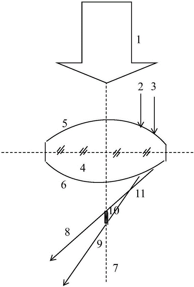
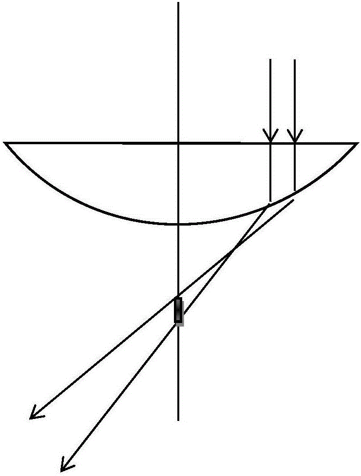
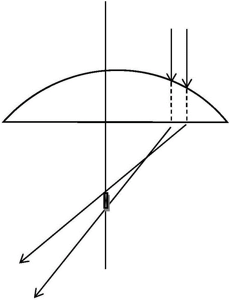
[0023] Such as figure 1 As shown, the present invention is a lens 4, which is characterized in that: the incident surface and the outgoing surface of the lens are both curved surfaces, and the incident light of any lateral distribution presents a uniform linear focus on the optical axis of the lens after being focused by the lens. spot. The lens 4 of the present invention is made of any optical material suitable for high-power laser transmission, and its incident surface 5 and outgoing surface 6 are curved surfaces, and the curved surfaces are aspherical. The laser beam 1 with any lateral distribution converges toward the optical axis 7 through the lens 4. In the laser beam 1, the ring composed of the inner circle ray 2 and the outer circle ray 3 passes through the optical lens 4 to produce refracted rays 9 and 8, and form a light beam paragraph 10. Refracted rays 8 and 9...


PUM


Abstract

The invention relates to an optical element achieving axial uniform linear focal spots. The optical element achieving the axial uniform linear focal spots is a lens or a reflector. At least one face of the lens or the reflector is a curved face. Incident rays which are distributed transversely at will are focused to the optical axis of the optical element through the lens or the reflector and show uniform linear focal spots. The curved face is an aspherical face. The axial uniform linear focal spots generated by the aspherical optical elements are not influenced by processing materials any more. The optical element achieving the axial uniform linear focal spots overcomes the defects that by the adoption of the 'filamentation' effect, the requirement for the processing materials is strict, the processing parameter 'window' is small, and the influence of material surfaces on the focal spots is large; and only one optical element is used for generation of the linear focal spots, processing of the element can be achieved through the prior art, and the complexity generated by a Bessel beam is overcome. The axial length of the linear focal spots is not limited theoretically, and the laser energy loss is the minimum. The optical element achieving the axial uniform linear focal spots overcomes the defects that the focal depth range of the Bessel beam is limited, and the peak power of the Bessel beam is low.

Description

technical field [0001] The invention relates to an optical device, in particular to a transmission or reflection device for changing the focusing characteristics of laser beams. Background technique [0002] The application fields of transparent or brittle materials such as glass, sapphire, and wafers are becoming more and more extensive. The most representative application fields are consumer electronics products, such as smart phone panels, camera protection windows, fingerprint recognition windows and other components. Transparent materials such as tempered glass and sapphire are used. Therefore, the effective and rapid processing of these materials has important practical significance. Traditional mechanical processing methods are slow, have severe edge chipping, and high consumables and costs, making it increasingly difficult to meet the increasing processing requirements of transparent or brittle materials. With the rapid development of laser technology, laser proces...

Claims


Application Information

Patent Timeline
Patent Type & Authority Applications(China)
IPC IPC(8): B23K26/073
CPCB23K26/0738
Inventor 熊政军陈涛
Owner 武汉澳谱激光科技有限公司
Learn More