Centrifugal feeding machine

A centrifugal and feeder technology, applied in the field of feeder, can solve the problems of loud noise, inability to adjust, and inability to replace the structure, and achieve the effect of low noise

Inactive Publication Date: 2017-05-24
NINGBO ZHUOCHENG AUTOMATION EQUIP
View PDF7 Cites 3 Cited by
  • Summary
  • Abstract
  • Description
  • Claims
  • Application Information

AI Technical Summary

Problems solved by technology

[0002] Parts feeding in mechanical processing is an important step before processing. However, due to the messy and irregular parts in the actual operation process, it is impossible to achieve high-efficiency feeding through manual work. At present, vibration feeding is usually used in the field of parts feeding. The feeder can transport a large number of semi-finished products processed by the upper position to the next step of the production line through the vibrating feeder
However, the noise generated by the vibrating work process of the vibrating machine in the prior art is too large, which easily affects the hearing of the on-site staff, and the vibration of the vibrating machine is the effect of a single vibrating fleet feeder, which not only consumes a lot of energy, but also The structure cannot be replaced and cannot be adjusted according to the change of screw size
[0003] For example, the Chinese patent with the invention application number 201520323415.2 discloses a centrifugal feeder, which is equipped with a first feeding tray group and a second feeding tray group, a fixed grid and a surrounding material grid group to cooperate with the first and second feeding trays. The disc pack is installed on the machine body; the first and second feed disc sets are driven by the first motor and the second motor of the machine body respectively to improve the noise generated during the bolt conveying process. It can also be used with the installation of the fixed grid and the fence group, and can be adjusted according to the size of the screw. However, this equipment still loads the material in a vertical manner after loading, which causes difficulties for the next process.

Method used


Image

  • Centrifugal feeding machine
  • Centrifugal feeding machine
  • Centrifugal feeding machine

Examples


Embodiment Construction

[0033] The present invention will be described in further detail below in conjunction with the accompanying drawings.

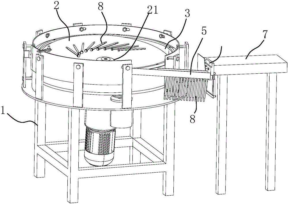
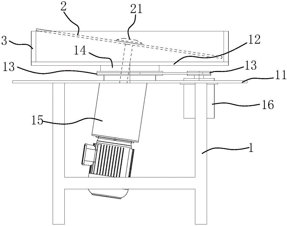
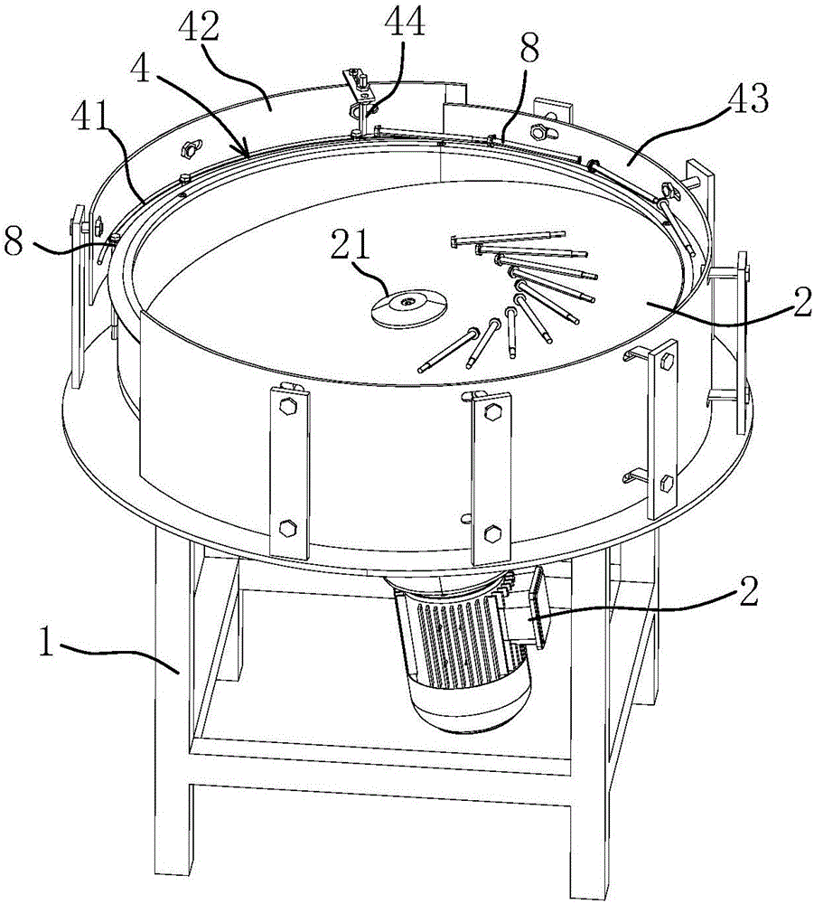
[0034] Please refer to the attached figure 1 , a centrifugal feeding machine, suitable for feeding scattered rod-shaped parts 8, such as fasteners that have not been threaded, including a frame 1, an inner turntable 2 is arranged above the frame 1, and An outer turntable 3 is arranged outside the turntable 2, wherein the inner turntable 2 and the outer turntable 3 are driven by independent motors, and a discharge track 4 is arranged outside the outer turntable 3, wherein unsorted fasteners are placed The centrifugal force is provided after the inner turntable 2 realizes the rotation, and the centrifugal force drives the fasteners into the discharge track 4, and is sent out along the discharge track 4 under the drive of the outer turntable 3, and enters the undetermined track 5, and is clamped The piece 6 is clamped into the straight feed channel 7 to realize...


PUM


Abstract

The invention discloses a centrifugal feeding machine. The problems that in the current screw feeding process, the noise is high, and the machining positions are inconvenient due to the vertical feeding mode are solved. The centrifugal feeding machine is characterized by comprising a machine frame; an inner turnplate is arranged on the machine frame; the inner turnplate is driven by a first driving device to rotate around the circle center; an outer turnplate which is driven by a second driving device to rotate around the circle center is arranged on the periphery of the inner turnplate; a discharging rail is arranged on the outer side of the outer turnplate; and a clamping piece is arranged between the tail end of a pending rail and a straight feeding channel and used for rotating vertically placed workpieces in the pending rail by 90 degrees and sequentially feeding the workpieces into the straight feeding channel. In this way, discharging of parts can be achieved through the centrifugal force, noise in the feeding process is reduced, in addition, finally, sequential transverse feeding can be achieved, and convenience is provided for subsequent machining.

Description

technical field [0001] The invention relates to a feeding machine, in particular to a feeding machine for feeding materials through the centrifugal force generated by equipment rotation. Background technique [0002] Parts feeding in machining is an important step before processing. However, due to the messy and irregular parts in the actual operation process, it is impossible to achieve high-efficiency feeding by manual work. At present, vibration feeding is usually used in the field of parts feeding. The feeder can transport a large number of semi-finished products processed by the host to the next step of the production line through the vibrating feeder. However, the noise generated by the vibrating work process of the vibrating machine in the prior art is too large, which easily affects the hearing of the on-site staff, and the vibration of the vibrating machine is the effect of a single vibrating fleet feeder, which not only consumes a lot of energy, but also The struc...

Claims


Application Information

Patent Timeline
Patent Type & Authority Applications(China)
IPC IPC(8): B23Q7/02B23Q7/04B23Q7/08
CPCB23Q7/02B23Q7/04B23Q7/08
Inventor 叶月勇
Owner NINGBO ZHUOCHENG AUTOMATION EQUIP
Why Eureka
Try Eureka