Fault detecting and processing method and device for braking assisting system

A technology for brake boosting and system failure, applied in the field of vehicles, can solve problems such as delay in failure detection scheme

Active Publication Date: 2017-05-24
BEIJING ELECTRIC VEHICLE
View PDF3 Cites 30 Cited by
  • Summary
  • Abstract
  • Description
  • Claims
  • Application Information

AI Technical Summary

Problems solved by technology

[0005] The purpose of the present invention is to provide a method and device for fault detection and processing of a brake

Method used


Image

  • Fault detecting and processing method and device for braking assisting system
  • Fault detecting and processing method and device for braking assisting system
  • Fault detecting and processing method and device for braking assisting system

Examples


Embodiment 1

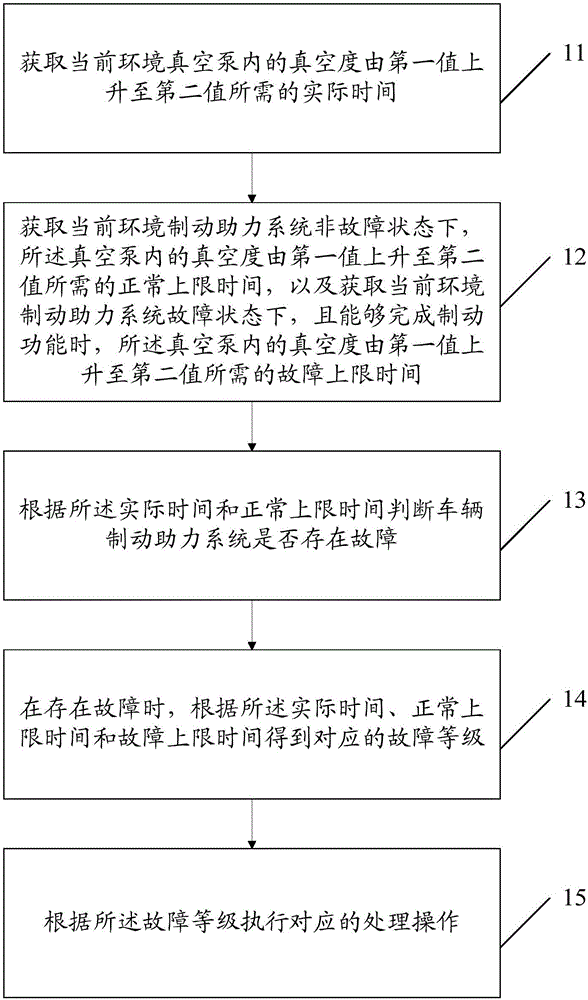
[0085] Such as figure 1 As shown, Embodiment 1 of the present invention provides a fault detection and processing method of a brake booster system, which can be applied to a vehicle, the vehicle includes a vacuum pump, and the brake booster system fault detection and processing method includes:

[0086] Step 11: Obtain the actual time required for the vacuum degree in the current ambient vacuum pump to rise from the first value to the second value;

[0087] Step 12: Obtain the normal upper limit time required for the vacuum degree in the vacuum pump to rise from the first value to the second value under the non-fault state of the current environment brake booster system, and obtain the current environment brake booster system failure state, And when the braking function can be completed, the upper fault limit time required for the vacuum degree in the vacuum pump to rise from the first value to the second value;

[0088] Step 13: According to the actual time and the normal up...

Embodiment 2

[0159] Such as Figure 7 As shown, Embodiment 2 of the present invention provides a brake booster system fault detection and processing device, which can be applied to a vehicle, the vehicle includes a vacuum pump, and the brake booster system fault detection and processing device includes:

[0160] The first obtaining module 71 is used to obtain the actual time required for the vacuum degree in the current environment vacuum pump to rise from the first value to the second value;

[0161] The second obtaining module 72 is used to obtain the normal upper limit time required for the vacuum degree in the vacuum pump to rise from the first value to the second value under the non-fault state of the brake boosting system in the current environment, and to obtain the brake boosting in the current environment When the system is in a fault state and the braking function can be completed, the fault upper limit time required for the vacuum degree in the vacuum pump to rise from the first...


PUM


Abstract

The invention provides a fault detecting and processing method and device for a braking assisting system. The fault detecting and processing method for the braking assisting system includes the steps that the needed actual time for increasing a first value to a second value of the vacuum degree in a vacuum pump in the current environment is obtained; the needed normal upper limit time for increasing the first value to the second value of the vacuum degree in the vacuum pump in the non-fault state of the braking assisting system in the current environment is obtained, and the needed fault upper limit time for increasing the first value to the second value of the vacuum degree in the vacuum pump in the fault state of the braking assisting system in the current environment when the braking function can be finished is obtained as well; whether a fault exists in the braking assisting system of a vehicle or not is judged according to the actual time and the normal upper limit time; if the fault exists, the corresponding fault level is obtained according to the actual time, the normal upper limit time and the fault upper limit time; and corresponding processing operation is executed according to the fault level. By the adoption of the scheme, the fault of the braking assisting system of the vehicle can be diagnosed in time, and the personal safety of a driver and passengers can be guaranteed to the largest degree.

Description

technical field [0001] The invention relates to the technical field of vehicles, in particular to a method and device for detecting and processing a brake booster system fault. Background technique [0002] In the face of increasingly severe energy and environmental problems, the increasing demand for oil resources and the environmental pollution caused by traditional fuel vehicles have increasingly attracted people's attention. At the same time, energy-saving and new energy vehicles are becoming research hotspots in various countries. As one of my country's strategic emerging industries, energy-saving and new energy vehicles have received great attention from the government and the industry. The development of new energy vehicles, especially pure electric vehicles with zero pollution and zero emissions, is not only important to my country's energy security and environmental protection. It is of great significance, and it is also an important direction for my country's automo...

Claims


Application Information

Patent Timeline
IPC IPC(8): B60T17/22
CPCB60T17/22
Inventor 李玮代康伟梁海强王亚楠
Owner BEIJING ELECTRIC VEHICLE
Why Eureka
Try Eureka