Plate winding machine and method for winding plate through plate winding machine

A winder and sheet technology, which is applied to the parts of bundling machinery, winding strips, and thin material processing, etc., can solve the problems of uneven side edges of sheet rolls, increased sheet tension, and uneven sheet tension.

Active Publication Date: 2017-05-24
河北吉玛自动化科技有限公司
7 Cites 3 Cited by

AI-Extracted Technical Summary

Problems solved by technology

The above-mentioned plate winder and winding method have the following defects: first, when the roll is changed, the plates are piled up, and the accumulated plates need to be straightened and re-coiled, which is time-consuming and laborious, and the accumulated plates fall on the ground and are easy to stick Dust affects the patent and appearance of the board; secondly, during the winding process, the weight of the board roll is light at the beginning, the friction between the board and the roller is small, and the tension of ...

Abstract

The invention belongs to the technical field of plate winding, and particularly relates to a plate winding machine and a method for winding a plate through the plate winding machine. The plate winding machine is mainly technically characterized in that a frame, a drawing mechanism, a feeding mechanism, a cutoff mechanism, a winding mechanism, a packing mechanism, a push-out mechanism and a packaging and weighing mechanism are included; the feeding mechanism is arranged behind the drawing mechanism; the cutoff mechanism is located at the rear end of the feeding mechanism; the winding mechanism is located at the rear end of the cutoff mechanism; the packing mechanism is located at the upper end of the winding mechanism; the packaging and weighing mechanism is located on one side of the winding mechanism; the winding mechanism comprises a fixed frame located at one end, a winding shaft and an ejector rod frame located at the other end; the winding shaft comprises a shaft core and multiple movable bearing bushes located on the outer side of the shaft core, and a fixed bearing bush is fixed to the outer side of one movable bearing bush through a fixing rod; and therefore before winding, the front end of the plate is automatically inserted into a clamping groove, the plate is automatically curled into a coil, the two sides of the plate coil are more orderly, and tension is consistent.

Application Domain

Bundling machine detailsIndividual articles +2

Technology Topic

Push outWinding machine +4

Image

  • Plate winding machine and method for winding plate through plate winding machine
  • Plate winding machine and method for winding plate through plate winding machine
  • Plate winding machine and method for winding plate through plate winding machine

Examples

  • Experimental program(1)

Example Embodiment

[0050] The structure and operating principle of the plate winder of the present invention will be further described in detail below in conjunction with the accompanying drawings.
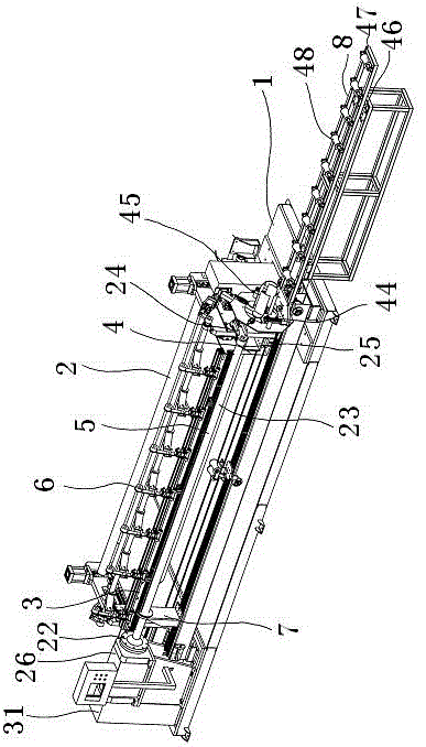
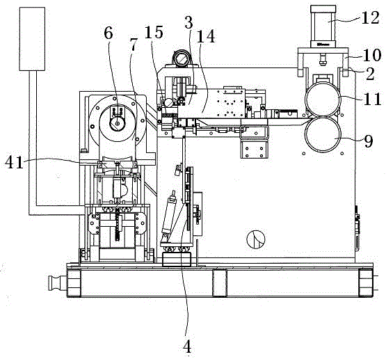
[0051] like figure 1 and figure 2 As shown, it is a schematic structural view of the plate winder of the present invention. The plate winder of the present invention includes a frame body 1, a traction mechanism 2, a feeding mechanism 3, a cutting mechanism 4, a winding mechanism 5, a packing mechanism 6, a pushing mechanism 7 and Packaging weighing mechanism 8, feeding mechanism 3 is arranged behind traction mechanism 2, cutting mechanism 4 is located at the rear end of feeding mechanism 3, winding mechanism 5 is located at the rear end of cutting mechanism 4, packaging mechanism 6 is located at the upper end of winding mechanism 5, and packaging weighing mechanism 8 Located on one side of the winding mechanism 5. The traction mechanism comprises a lower traction shaft 9 fixed with the frame body 1, an upper traction shaft fixed mount 10 is arranged above the lower traction shaft 9, an upper traction shaft 11 is arranged on the upper traction shaft fixed mount 10, and the upper traction shaft 11 is connected with The upper traction shaft fixed mounts 10 are connected by the first pressing cylinder 12 .
[0052] like figure 1 , image 3 , Figure 4 and Figure 5 As shown, the feeding mechanism 3 includes a traveling track 13 positioned on the frame body 1 and a feeding frame 14 matched with the feeding track. A forward and backward mechanism 15 is arranged between the frame body 1 and the feeding frame 14. A lower clamping bar 16 is arranged, and an upper clamping bar 17 which can be lifted up and down is arranged above the lower clamping bar 16 .
[0053] like Image 6 and Figure 7 Shown, cutting mechanism 4 comprises the cutting track 18 that is fixed with frame body 1, is provided with first elevating mechanism 19 on cutting track 18, is provided with cutter frame 20 at this first elevating mechanism 19 upper ends, is provided with cutter frame 20 A cutter 21 is arranged above.
[0054] like figure 1 and Figure 8 As shown, the winding mechanism 5 includes a fixed mount 22 at one end, a winding shaft 23 and a push rod frame 24 positioned at the other end. The end of the push rod frame 24 can swing on the frame body 1. One side of the fixed frame 22 is provided with a power mechanism 26 that is dynamically connected to the winding shaft 23. The winding shaft 23 includes a shaft core 27 and a plurality of movable bearing bushes 28 located outside the shaft core 27. The shaft core 27 is connected, and the air pressure ejector rod 29 is controlled and connected with the cylinder 31 through the air hole 30 in the middle of the shaft core 27. A fixed bearing pad 33 is fixed on the outside of one of the movable bearing pads 28 through a fixed rod 32. Clamping grooves 34 are formed between the movable bearing shells 28 .
[0055] like figure 1 As shown, the packaging mechanism 6 includes a tape holder 35 and a tape cutter mechanism 36 , and a tape shaft 37 is arranged on the tape holder 35 , and the tape holder 35 is connected to the frame body 1 through a second lifting mechanism 38 .
[0056] like figure 1 , Figure 9 and Figure 10 As shown, the push-out mechanism 7 includes a lifting slideway 39 and a discharge push plate 40 positioned below the winding shaft 23, a lifting mechanism 41 is arranged on the lifting slideway 39, and a lifting pulley is arranged above the lifting mechanism 41. 42 , the unloading push plate 40 is sleeved on the winding shaft 23 , and the initial position is located on the side of the fixed frame 22 , and a groove 43 is provided on the unloading push plate 40 .
[0057] like figure 1 As shown, the packaging and weighing mechanism 8 includes a stretch ring 44 located at one end of the winding shaft 23, a packaging bag 45 is arranged on the stretch ring 44, and a roller frame with a gravity sensor 46 is arranged below the side of the stretch ring 44 47, the idler roller frame 47 is provided with a weighing idler 48.
[0058]First pass the board between the upper traction shaft 11 and the lower traction shaft 9, reset the feeding frame 14, and at the same time move up the upper clamping bar 17, and send the front end of the plate to the upper clamping bar 17 and the lower clamping bar 16 through the traction mechanism 2 At the front end, press down the upper clamping bar 17, so that the upper clamping bar 17 and the lower clamping bar 16 clamp the plate, and the first lifting mechanism 19 controls the top of the cutter frame 20, so that the cutter 21 is inserted into the plate, and along the cutting track 18 Move the cutter frame 20 laterally to cut the front end of the plate neatly; move the cutter frame 20 down, move the upper clamping bar 17 up, and then pull the plate forward through the traction mechanism 2, so that the plate protrudes out of the front end of the clamping bar The ratio of the length to the depth of the clamping groove 34 on the winding shaft is 1:4—1:1, and then the upper clamping bar 17 is moved down so that the upper clamping bar 17 and the lower clamping bar 16 clamp the plate; The winding shaft 23 resets, exhausts air through the air hole 30, and retracts the movable bearing bush 28. At this time, the front end of the clamping groove 34 points to the incoming direction of the plate, and the forward and backward mechanism 15 controls the feeding frame 14 to move forward, and the upper clamping bar 17 And the lower clamping bar 16 drives the front end of the plate to be inserted into the clamping groove 34; through the cylinder 31, the air pressure ejector rod 29 is controlled to rise, driving the movable bearing bush 28 to move upward, the clamping groove 34 is narrowed, and the front end of the plate is clamped, while the upper clamping bar 17 moves up, and feeding rack 14 retreats to original position. The traction mechanism 2 pulls the plate forward, and at the same time the winding shaft 23 rotates to wind the plate on the winding shaft 23; when the winding of the plate reaches the set length, the traction mechanism 2 stops pulling the plate forward, the winding shaft 23 stops rotating, and the upper clamp The holding bar 17 moves down to clamp the plate. At this time, the first lifting mechanism 19 controls the top of the cutter frame 20 so that the cutter 21 is inserted into the plate, and the cutter frame 20 is moved laterally along the cutting track 18 to cut the plate. Through the second lifting mechanism 38, the tape shaft 37 is controlled to move down, so that the adhesive tape on the tape shaft 37 is attached to the plate outside the winding shaft 23, and the winding shaft 23 is rotated to wrap the tape on the outside of the plate; after reaching the number of winding turns, pass The tape cutter mechanism 36 cuts the tape. Rotate the winding shaft 23 to align the fixed bearing bush 33 on the winding shaft 23 with the groove 43 on the unloading push plate 40, lift the lifting mechanism 41 below the winding shaft 23 to the bottom of the plate roll, and control the air pressure jacking through the cylinder 31 The rod 29 and the movable bearing bush 28 shrink, and the outer side of the movable bearing bush 28 is separated from the inner side of the plate roll; the ejector rod frame 24 is swung outward, so that the ejector rod 25 is separated from the end of the winding shaft, and at the same time, the end of the packaging bag 45 is fixed on the tension ring 44 , the plate roll is pushed out onto the idler frame 47 by the unloading push plate 40, and the packaging bag is packed to the outside of the plate roll at the same time; the weight of the plate roll is calculated by the gravity sensor 46, and the label is then attached to the packaging bag 45; start over Wind the next roll. In this way, before winding, the front end of the plate is automatically inserted into the clamping groove, and it is automatically curled into a roll. The two sides of the plate roll are more neat and the tension is consistent, which saves manpower and material resources.
[0059] The movable bearing bush 28 is 5 pieces, and it is more convenient to release.
[0060] The method of using the above-mentioned sheet material winding machine to carry out sheet material winding, the method includes the following steps:
[0061] The first step is to trim the front end of the board
[0062] Pass the plate between the upper traction shaft 11 and the lower traction shaft 9, reset the feeding frame 14, and at the same time move the upper clamping bar 17 up, and send the front end of the plate to the front end of the upper clamping bar 17 and the lower clamping bar 16 through the traction mechanism 2 , press down the upper clamping bar 17, so that the upper clamping bar 17 and the lower clamping bar 16 clamp the plate, the first lifting mechanism 19 controls the upper top of the cutter frame 20, so that the cutter 21 is inserted into the plate, along the cutting track 18 Move the cutter frame 20 laterally to cut the front end of the plate neatly;
[0063] In the second step, the front end of the plate protrudes from the front end of the upper clamping bar and the lower clamping bar
[0064] Move the cutter frame 20 down, move the upper clamping bar 17 up, and then pull the plate forward through the traction mechanism 2, so that the ratio of the length of the plate protruding from the front end of the clamping bar to the depth of the clamping groove 34 on the winding shaft 1:4—1:1, then move the upper clamping bar 17 down so that the upper clamping bar 17 and the lower clamping bar 16 clamp the plate;
[0065] The third step is to insert the front end of the plate into the clamping groove
[0066] Reset the winding shaft 23, exhaust air through the air hole 30, and retract the movable bearing bush 28. At this time, the front end of the clamping groove 34 points to the incoming direction of the plate, and the forward and backward mechanism 15 is used to control the forward movement of the feeding frame 14, and the upper clamping bar 17 and the lower clamping strip 16 drive the front end of the plate to be inserted into the clamping groove 34;
[0067] The fourth step is to clamp the front end of the plate
[0068] The air pressure ejector rod 29 is controlled by the cylinder 31 to rise, and the movable bearing bush 28 is moved upward, the clamping groove 34 is narrowed, and the front end of the plate is clamped. At the same time, the upper clamping bar 17 is moved upward, and the feeding frame 14 is retreated to the original position;
[0069] The fifth step, sheet winding
[0070] The traction mechanism 2 pulls the sheet to move forward, and at the same time the winding shaft 23 rotates to wind the sheet on the winding shaft 23;
[0071] Step six, cut off
[0072] When the plate winding reaches the set length, the traction mechanism 2 stops pulling the plate forward, the winding shaft 23 stops rotating, and the upper clamping bar 17 moves down to clamp the plate. At this time, the first lifting mechanism 19 controls the cutting tool frame 20 to top, so that the cutter 21 is inserted into the plate, and the cutter frame 20 is moved laterally along the cutting track 18 to cut the plate;
[0073] Step seven, packing
[0074] Through the second lifting mechanism 38, the tape shaft 37 is controlled to move down, so that the adhesive tape on the tape shaft 37 is attached to the plate outside the winding shaft 23, and the winding shaft 23 is rotated to wrap the tape on the outside of the plate; after reaching the number of winding turns, pass Tape cutter mechanism 36 cuts off the tape;
[0075] The eighth step, shrink the movable bearing
[0076] Rotate the winding shaft 23 to align the fixed bearing bush 33 on the winding shaft 23 with the groove 43 on the unloading push plate 40, lift the lifting mechanism 41 below the winding shaft 23 to the bottom of the plate roll, and control the air pressure jacking through the cylinder 31 The rod 29 and the movable bearing bush 28 shrink, and the outer side of the movable bearing bush 28 is separated from the inner side of the plate roll;
[0077] The ninth step, unload the volume
[0078] Swing the ejector rod frame 24 outwards so that the ejector rod 25 is separated from the end of the winding shaft, and at the same time fix the end of the packaging bag 45 on the tension ring 44, and push the plate roll onto the roller frame 47 through the unloading push plate 40, At the same time, pack the packaging bag to the outside of the plate roll;
[0079] Step ten, weigh and mark
[0080] Calculate the plate roll weight by the gravity sensor 46, and then stick the label on the packaging bag 45;
[0081] The eleventh step, continue to wrap
[0082] Repeat from step two to start over with the next roll.
[0083] The scope of protection of the present invention is not limited to the above-mentioned embodiments, as long as the structure is the same or similar to that of the plate winder of the present invention, it falls within the scope of protection of the present invention.

PUM

no PUM

Description & Claims & Application Information

We can also present the details of the Description, Claims and Application information to help users get a comprehensive understanding of the technical details of the patent, such as background art, summary of invention, brief description of drawings, description of embodiments, and other original content. On the other hand, users can also determine the specific scope of protection of the technology through the list of claims; as well as understand the changes in the life cycle of the technology with the presentation of the patent timeline. Login to view more.
Why Eureka
Try Eureka