
Efficient hot dipping device

A hot-dip plating, high-efficiency technology, applied in hot-dip plating process, metal material coating process, coating and other directions, can solve problems such as unreasonable structural design, coating peeling, and unreasonable hot-dip plating process.

Active Publication Date: 2017-05-24
FUDA SPECIAL STEEL GROUP WORKS JIANGSU
View PDF2 Cites 2 Cited by
  • Summary
  • Abstract
  • Description
  • Claims
  • Application Information

AI Technical Summary

Problems solved by technology

[0002] Hot-dip galvanizing is a steel plate surface protection technology, which is widely used in the protection of steel. The use of hot-dip galvanizing can achieve effective protection and improve performance of steel. With the development of science and technology, the types of hot-dip galvanizing equipment are also becoming more and more The more people have higher and higher requirements for the quality of the coating, no matter what kind of hot dip coating equipment is used, the process used in the hot dip coating has a great impact on the quality of the coating. In the prior art, different heat The structural limitation of the dipping equipment makes the hot dipping process different. Therefore, due to the unreasonable hot dipping process in the existing production, the unreasonable structural design of the hot dipping equipment often causes the coating uniformity and structure The structure is unstable, which leads to a series of problems such as peeling and cracking of the coating

Method used


Image

  • Efficient hot dipping device

Examples


Embodiment Construction

[0011] The high-efficiency hot-dip coating device of the present invention will be described in further detail below in conjunction with the accompanying drawings and specific embodiments.

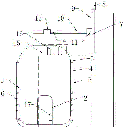
[0012] As shown in the figure, the high-efficiency hot-dip coating device of the present invention includes a hot-dip coating furnace 1 and a ceramic crucible 2 placed in the hot-dip coating furnace for hot-dipping parts to be coated, and the outer wall of the hot-dip coating furnace has Jacket 3, the jacket 3 has upper and lower layers, the upper jacket is set as an air chamber 4, the top of the hot dip coating furnace is provided with a blowing port 5 communicating with the air chamber 4, and the lower jacket is provided with a The heating coil 6 for heating in the coating furnace, a column 7 is arranged on one side of the hot-dip coating furnace 1, and a lifting screw 8 driven by a lifting motor is installed on the column 7, and the two sides of the lifting screw 8 have parallel installa...


PUM


Abstract

The invention discloses an efficient hot dipping device. The efficient hot dipping device comprises a hot dipping furnace and a crucible. A jacket is arranged on the outer wall of the hot dipping furnace and provides with an upper jacket layer and a lower jacket layer. An air cavity is formed in the upper jacket layer. An air blowing nozzle is formed in the top of the hot dipping furnace. A heating coil pipe is arranged in the lower jacket layer. A stand column is arranged on one side of the hot dipping furnace. A lifting lead screw is installed on the stand column. Two guide rails are installed on the two sides of the lifting lead screw. A horizontal sliding rod is installed on the lifting lead screw. Sliding blocks are arranged on the two sides of the horizontal sliding rod. A plated part hanging device is arranged on the horizontal sliding rod. A plated part stretching into the hot dipping furnace can be hung on the plated part hanging device. By the adoption of the structure, the uniformity of a plating layer and the stability of structures are improved, fast cooling can be conducted on the plated part which is subjected to hot dipping and cooled with air, thus, the hot dipping effect is further guaranteed, the problem that a plating layer is non-uniform is completely solved, and the quality of the plating layer is improved.

Description

technical field [0001] The invention relates to a hot-dip coating technology, in particular to a high-efficiency hot-dip coating device. Background technique [0002] Hot-dip galvanizing is a steel plate surface protection technology, which is widely used in the protection of steel. The use of hot-dip galvanizing can achieve effective protection and improve performance of steel. With the development of science and technology, the types of hot-dip galvanizing equipment are also becoming more and more The more people have higher and higher requirements for the quality of the coating, no matter what kind of hot dip coating equipment is used, the process used in the hot dip coating has a great impact on the quality of the coating. In the prior art, different heat The structural limitation of the dipping equipment makes the hot dipping process different. Therefore, due to the unreasonable hot dipping process in the existing production, the unreasonable structural design of the ho...

Claims


Application Information

Patent Timeline
Patent Type & Authority Applications(China)
IPC IPC(8): C23C2/00
Inventor 顾炳福朱丽慧
Owner FUDA SPECIAL STEEL GROUP WORKS JIANGSU
Learn More