A kind of ventilation shaft of urban underground comprehensive utility gallery

A technology of integrated pipe gallery and ventilation shaft, which is applied to underwater structures, buildings, artificial islands, etc., can solve the problems of shallow covering depth, unable to meet the requirements of road pavement setting, and unable to meet the setting requirements of ventilation interlayer 41', etc. The effect of saving setting space

Active Publication Date: 2019-07-05
MCC CAPITAL ENGINEERING & RESEARCH
View PDF5 Cites 0 Cited by
  • Summary
  • Abstract
  • Description
  • Claims
  • Application Information

AI Technical Summary

Problems solved by technology

like Image 6 As shown, but because the sewage pipeline inside the sewage tank 1' is a gravity flow pipeline, affected by the elevation of the sewage pipeline, in many cases, the covering soil depth h1 above the sewage tank 1' is relatively shallow, which cannot meet the setting requirements of the ventilation interlayer 41' , causing the ventilation interlayer 41' to fail to meet the road pavement setting requirements, or highlight the green belt

Method used


Image

  • A kind of ventilation shaft of urban underground comprehensive utility gallery
  • A kind of ventilation shaft of urban underground comprehensive utility gallery
  • A kind of ventilation shaft of urban underground comprehensive utility gallery

Examples


Embodiment Construction

[0035] In order to have a clearer understanding of the technical features, purposes and effects of the present invention, the specific implementation manners of the present invention will now be described with reference to the accompanying drawings.

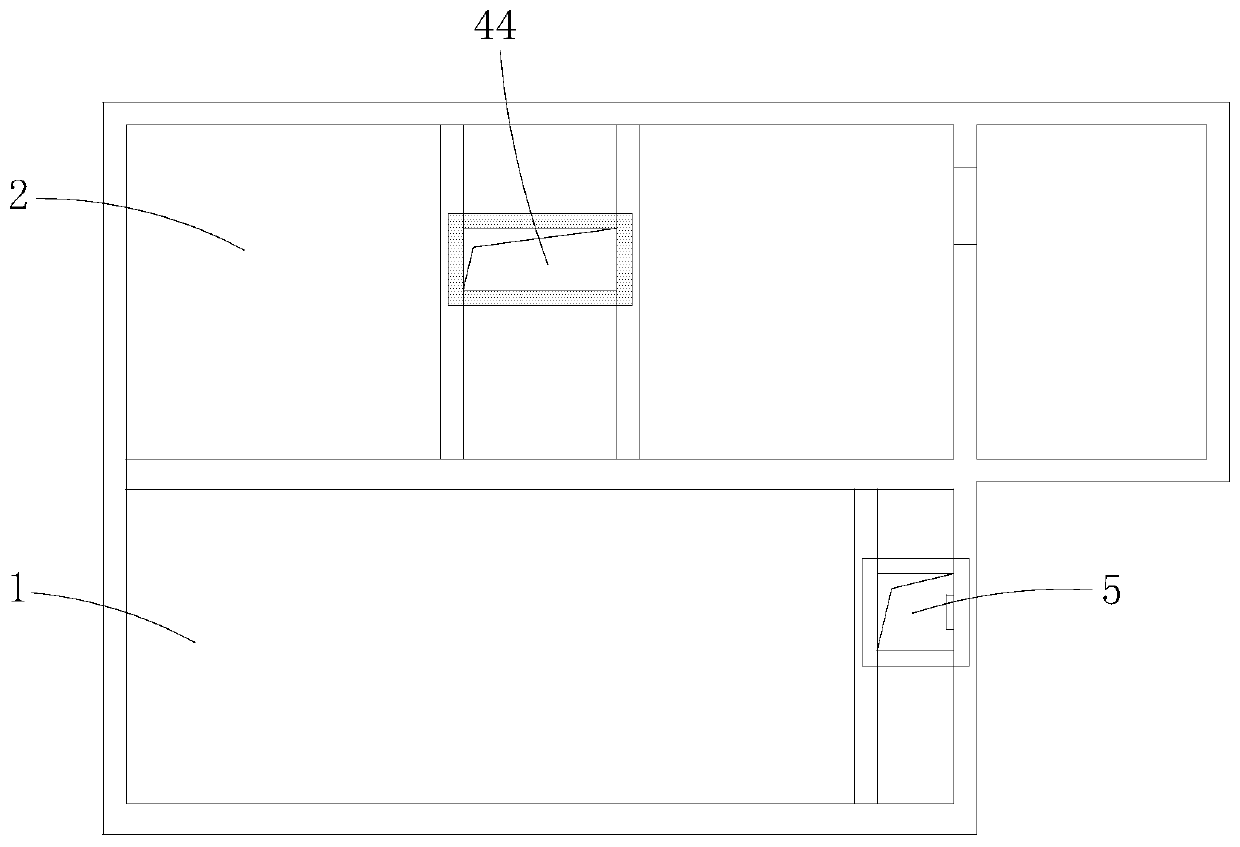
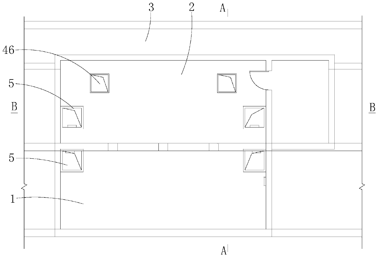
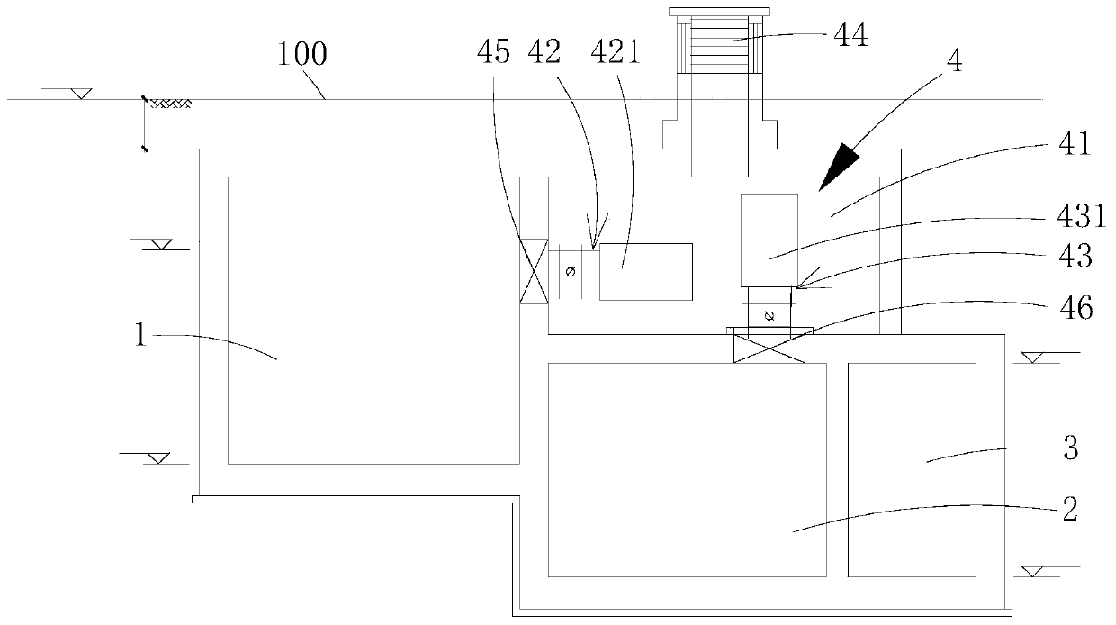
[0036] Such as figure 1 , figure 2 , image 3 As shown, the present invention provides a kind of ventilation shaft of urban underground comprehensive utility gallery, and it comprises the shared ventilation shaft 4 that can connect the sewage tank 1 and the hydropower cabin 2 of the comprehensive utility gallery with the outside (above the ground) of the comprehensive utility gallery, the sewage cabin 1 and the hydroelectric cabin 2 are set side by side and sealed and isolated. The sewage cabin 1 is higher than the hydroelectric cabin 2, that is, the sewage cabin 1 and the hydroelectric cabin 2 are arranged in staggered layers to form a height difference. The top wall of the sewage cabin 1 is higher than the hydroelectric cabi...


PUM


Abstract

The invention provides an urban underground utility tunnel ventilating shaft. The urban underground utility tunnel ventilating shaft comprises a shared ventilating shaft which can communicate a sewage bin and a hydroelectric bin of a utility tunnel with the outside of the utility tunnel; the sewage bin and the hydroelectric bin are arranged parallelly and are separated from each other in a sealed manner; and the shared ventilating shaft comprises a sewage bin ventilating hole which is formed in the side wall of the sewage bin and is located above the hydroelectric bin, a hydroelectric bin ventilating hole which is formed in the top wall of the hydroelectric bin, a shared ventilating interlayer which is arranged above the hydroelectric bin, is located below the ground, and communicates with the sewage bin ventilating hole and the hydroelectric bin ventilating hole, a sewage bin ventilating component and a hydroelectric bin ventilating component which are both located in the shared ventilating interlayer and a shared ventilating opening which communicates with the shared ventilating interlayer and extends above the ground, wherein the sewage bin ventilating component is arranged at the sewage bin ventilating hole, and the hydroelectric ventilating component is arranged at the hydroelectric bin ventilating hole. By adopting the utility tunnel ventilating shaft, an elevation requirement of a sewage pipeline can be met, and requirement of the ventilating interlayer on a covering depth can also be met.

Description

technical field [0001] The invention relates to the technical field of urban underground facilities, in particular to a ventilation shaft of an urban underground comprehensive utility gallery. Background technique [0002] According to the requirements of urban construction, all kinds of pipelines must enter the corridor in the construction of a comprehensive pipeline corridor area, and the pipelines include gas pipelines, sewage pipelines, etc. [0003] In order to ensure a good operating environment inside the pipe gallery, it is necessary to set up a ventilation shaft that communicates with the outside of the pipe gallery. Combined with relevant engineering examples, the designed soil covering depth of the pipe corridor cabin (except the sewage tank) is about 3 meters, which can meet the setting requirements of the ventilation interlayer 41' of the ventilation shaft. Such as Figure 6 As shown, but because the sewage pipeline inside the sewage tank 1' is a gravity flow p...

Claims


Application Information

Patent Timeline
Patent Type & Authority Patents(China)
IPC IPC(8): E02D29/045E02D29/00
CPCE02D29/10
Inventor 蒋晓昊陈思侯建强齐临冬张伟娜
Owner MCC CAPITAL ENGINEERING & RESEARCH
Why Eureka
Try Eureka