Tool for mining machinery equipment
A technology of mining equipment and knives, which is applied in the field of knives on mining machinery and equipment, can solve the problems of complex manufacturing process, inconvenient replacement, high maintenance costs, etc., and achieve the effects of low process cost, long service life, and reduced noise troubles
- Summary
- Abstract
- Description
- Claims
- Application Information
AI Technical Summary
Problems solved by technology
Method used
Image

Examples
Embodiment 1
[0029] Embodiment 1: A cutter for mining equipment, including a cutter seat 1 and a cutter head, wherein the cutter head has a linear cutting edge.
[0030] Using the cutting tool for mining equipment in this embodiment, it is possible to mine ore with a Platinum hardness coefficient of 15, such as very strong granite, and to process the ore to a particle size of 60 mm.
Embodiment 2
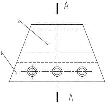
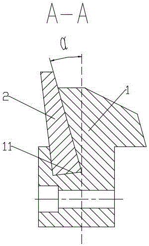
[0031] Embodiment 2: as figure 1 and figure 2 As shown, a cutter for mining equipment includes a cutter holder 1 on which a blade 2 is installed.
[0032] Wherein, a mounting groove 11 is provided on the knife seat 1 , and the blade 2 is mounted in the mounting groove 11 . The cross-section of the installation groove 11 has a narrow top and a wide bottom. In this embodiment, the cross section of the installation groove 11 is L-shaped. The cross section of the blade 2 is L-shaped matching the cross section of the installation groove 11 .
[0033] During installation, the blade 2 is inserted into the installation groove 11 from the side of the installation groove 11, and then the blade 2 and the installation groove 11 are fixedly bonded together with metal glue.
[0034] Using the cutting tool for mining equipment in this embodiment, it is possible to mine ores with a Platinum hardness coefficient above 15, such as very strong quartzite, and to process the ores to a particl...
Embodiment 3
[0036] Embodiment 3: as figure 1 and figure 2 As shown, a cutter for mining equipment includes a cutter holder 1 on which a blade 2 is installed.
[0037] Wherein, a mounting groove 11 is provided on the knife seat 1 , and the blade 2 is mounted in the mounting groove 11 . The cross-section of the installation groove 11 has a narrow top and a wide bottom. In this embodiment, the cross section of the installation groove 11 is an inverted T shape. The cross-section of the blade 2 is an inverted T shape matched with the cross-section of the installation groove 11 .
[0038] During installation, the blade 2 is put into the installation groove 11 from the side of the installation groove 11, and then the blade 2 and the installation groove 11 are welded together by welding.
[0039] Using the cutting tool for mining equipment in this embodiment, it is possible to mine ores with a Platinum hardness coefficient above 15, such as the most solid granite, and to process the ores to ...
PUM
 Abstract
Description
Claims
Application Information
 - R&D
- Intellectual Property
- Life Sciences
- Materials
- Tech Scout
- Unparalleled Data Quality
- Higher Quality Content
- 60% Fewer Hallucinations
Browse by: Latest US Patents, China's latest patents, Technical Efficacy Thesaurus, Application Domain, Technology Topic, Popular Technical Reports.
© 2025 PatSnap. All rights reserved.Legal|Privacy policy|Modern Slavery Act Transparency Statement|Sitemap|About US| Contact US: help@patsnap.com