Engine

An engine and wind-driven technology, which is applied in the direction of engine components, engine cooling, machine/engine, etc., can solve problems such as difficult to withstand high temperature, extremely high material requirements, and affect the thrust efficiency of aeroengines, so as to achieve high thrust efficiency and simple structure Effect

Inactive Publication Date: 2017-05-24
SHANGLING CO LTD
View PDF5 Cites 0 Cited by
  • Summary
  • Abstract
  • Description
  • Claims
  • Application Information

AI Technical Summary

Problems solved by technology

[0002] Traditional aero-engines have extremely high requirements on materials, and they are diffi

Method used


Image

  • Engine
  • Engine
  • Engine

Examples


Embodiment 1

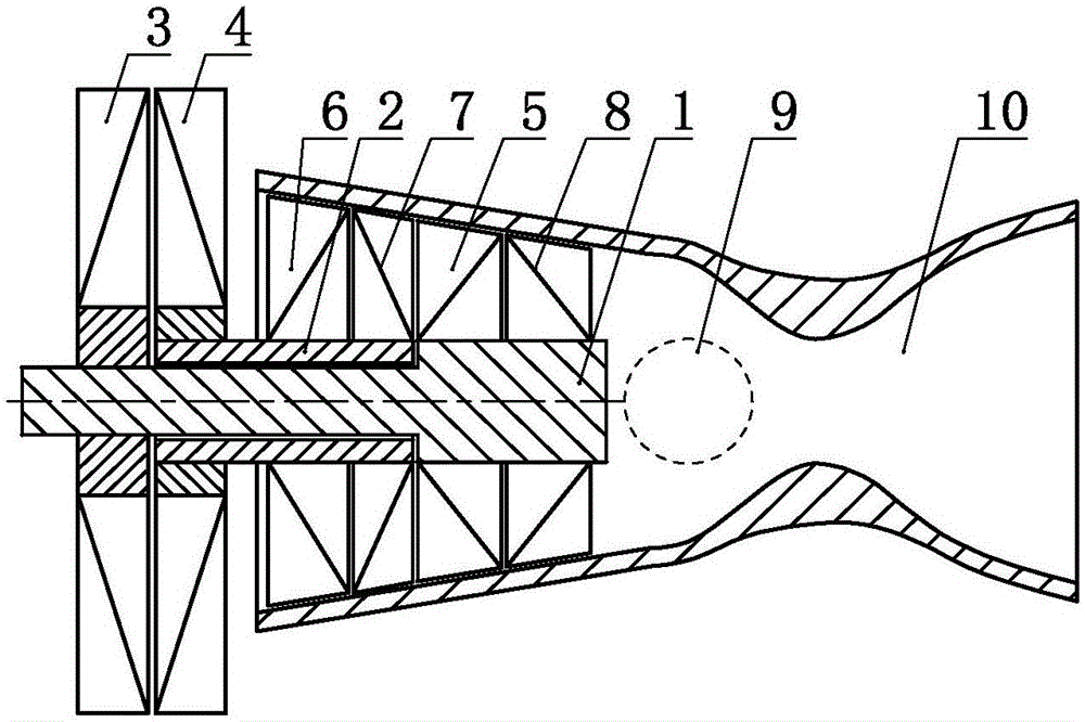
[0037] an engine such as figure 1 As shown, including power shaft A 1, power shaft B 2, wind turbine impeller A3, wind turbine impeller B 4, compressor impeller A 5, compressor impeller B 6, compressor impeller C 7, compressor impeller D 8, combustion chamber 9 and nozzle 10, the power shaft B 2 is sleeved outside the power shaft A 1, the compressor impeller A 5 is set on the power shaft A 1, and the wind turbine impeller A 3 is connected to the power shaft A 1. The power shaft A1 is set for transmission, the compressor impeller B6 is set on the power shaft B2, the wind turbine impeller B4 is set for transmission with the power shaft B2, and the compressor impeller C7 It is arranged on the power shaft B2, the compressor impeller D8 is arranged on the power shaft A1, the compressor impeller B6, the compressor C7, the compressor A5 and the compressor The impellers D 8 are sequentially connected in series, and the compressed gas outlet of the compressor impeller D 8 communicates...

Embodiment 2

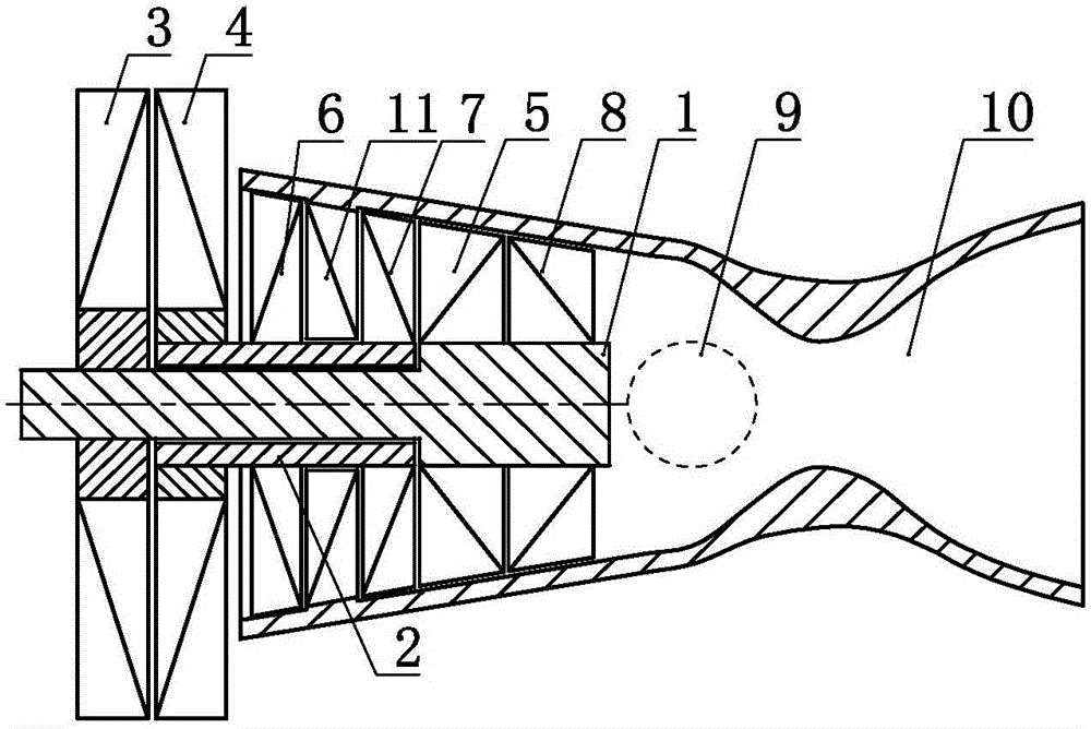
[0040] an engine such as figure 2 As shown, the difference from Embodiment 1 is that a stationary guide impeller 11 is provided between the compressor impeller B 6 and the compressor impeller C 7 .

[0041] As a transformable embodiment, embodiment 1 of the present invention and its transformable embodiment and embodiment 2 can further selectively select the wind turbine blade A 3 and the wind turbine blade B 4 Co-rotation setting or counter-rotation setting.

Embodiment 3

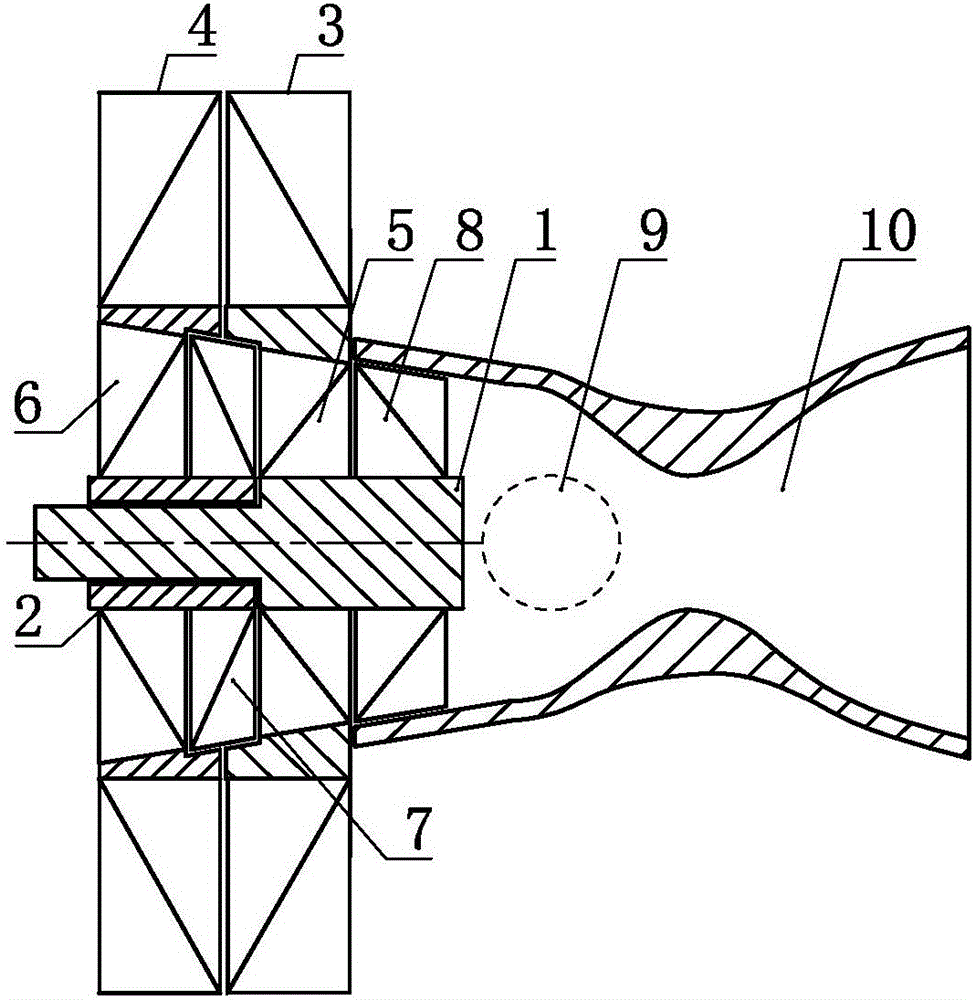
[0043] an engine such as image 3 As shown, including power shaft A 1, power shaft B 2, wind turbine impeller A3, wind turbine impeller B 4, compressor impeller A 5, compressor impeller B 6, compressor impeller C 7, compressor impeller D 8, combustion chamber 9 and nozzle 10, the power shaft B 2 is sleeved outside the power shaft A 1, the compressor impeller A 5 is set on the power shaft A 1, and the wind turbine impeller A 3 is connected to the power shaft A 1. The power shaft A1 is set for transmission, the compressor impeller B6 is arranged on the power shaft B2, the compressor impeller C7 is arranged on the power shaft B2, and the compressor impeller D8 is arranged on the On the power shaft A1, the compressed air impeller B6, the compressed air impeller C7, the compressed air impeller A5 and the compressed air impeller D8 are sequentially connected in series, and the compressed gas outlet of the compressed air impeller D8 passes through the The combustion chamber 9 commun...


PUM


Abstract

The invention discloses an engine which comprises a pneumatic turbine impeller A, a pneumatic turbine impeller B, a compressor impeller A, a compressor impeller B, a combustion chamber and a spraying pipe. The pneumatic turbine impeller A and the pneumatic turbine impeller B are arranged in a counter rotating mode. The pneumatic turbine impeller A and the compressor impeller A are arranged in a transmission mode. The pneumatic turbine impeller B and the compressor impeller B are arranged in a transmission mode. The compressor impeller A and the compressor impeller B communicate with each other in a series connection mode. A compressed gas outlet of the compressor impeller B communicates with the spraying pipe through the combustion chamber. The engine has the advantages of being simple in structure and high in thrust efficiency.

Description

technical field [0001] The invention relates to the field of thermal energy and power, especially to an engine. Background technique [0002] Traditional aero-engines have extremely high requirements on materials, and they are difficult to withstand high temperatures, which seriously affects the thrust efficiency of aero-engines. Therefore need to invent a kind of new engine. Contents of the invention [0003] In order to solve the above problems, the technical scheme proposed by the present invention is as follows: [0004] A kind of engine of the present invention comprises power shaft A, power shaft B, wind-driven turbine impeller A, wind-driven turbine impeller B, compressed air impeller A, compressed air impeller B, compressed air impeller C, compressed air impeller D, combustion chamber and nozzle tube, the power shaft B is set outside the power shaft A, the compressor impeller A is set on the power shaft A, the wind turbine impeller A is set in transmission with t...

Claims


Application Information

Patent Timeline
IPC IPC(8): F02K5/00F02C7/12
CPCF02K5/00F02C7/12
Inventor 靳北彪
Owner SHANGLING CO LTD
Why Eureka
Try Eureka